Eng-Tips is the largest engineering community on the Internet

Intelligent Work Forums for Engineering Professionals

Help needed with FE model check failures

Status
Not open for further replies.

ShireenBB

Aerospace
Apr 13, 2023
9
0
0
CA
Hello,

I have questions regarding FE modelling with rbe2, rbe3, and solid elements. I keep getting failures in my unit gravity and free free checks, and the points of exceedances are beams connected to rbe2 elements.
My questions are are follows:
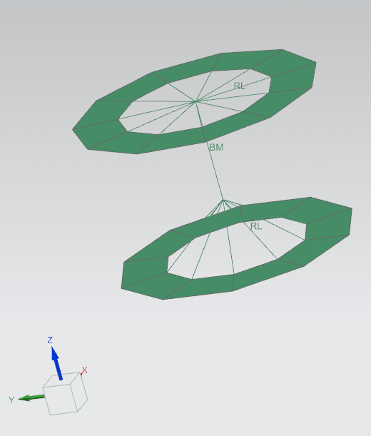
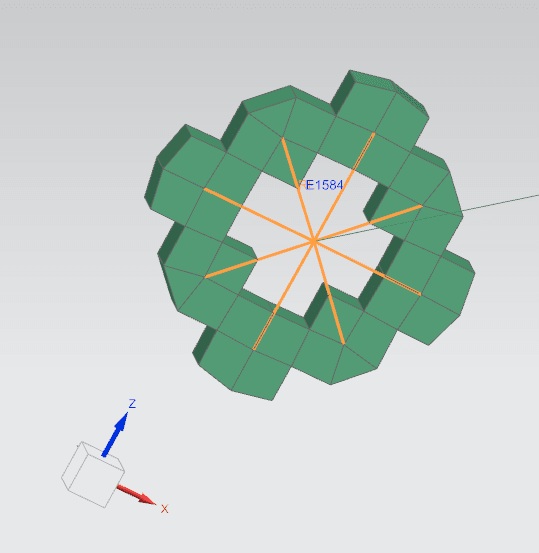
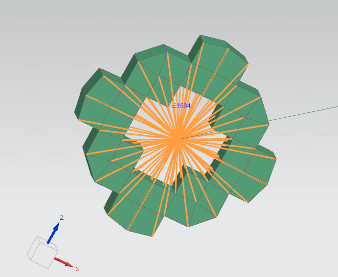
1) What is the best way to connect 2 rbe2 spiders that are not coincident? Right now they are connected with CBEAM elements but I still seem to have errors.
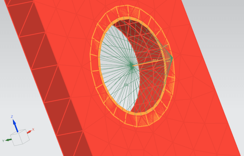
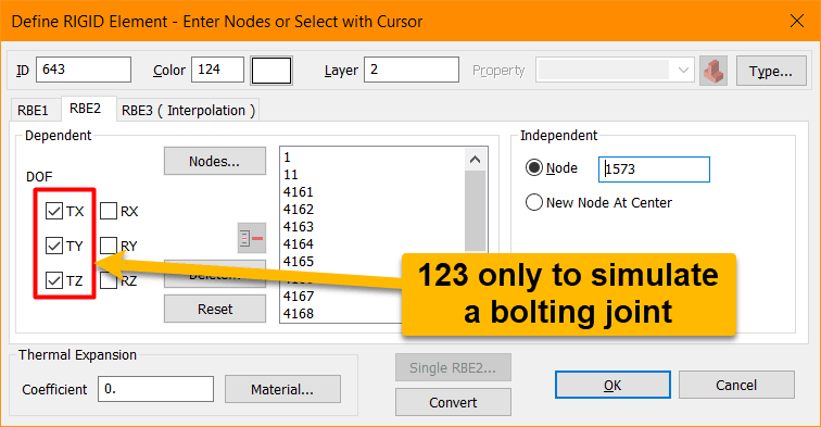
2) Is it ok to connect rbe2 elements to solid elements, or do special measures have to be taken? My understanding is that solid elements only have stiffness in translational degrees of freedom, so how is the rotational forces transferred between the rbe2 and solid element?
3) What is the best way to find out why my model checks are failing? I have animated the free free checks but nothing seems to be lose. I seem to have 6 rigid modes and then flexible modes.

Thank you very much- I would appreciate assistance in this urgent matter!
 
Replies continue below

Recommended for you

Please do not double post; flag your other post for deletion.

Post pictures of your model and the rigid elements. Very hard to understand without those.
 
Rbe2-beam-plate_connection_q4maib.png
Rbe2-beam-solid_connection_dtd234.png
 
Kind of hard to tell what is connected:

Rbe2-beam-solid_connection_ix1cgu.png


But you cannot connect dependent nodes of two rigid elements to the same node.

Are the independent nodes for each rigid element connected to the beam element?
 
Hello!,
Attached a nastran input deck with rigid RBE2 elements with a bolt meshed with CBEAM elements to joint two solid components meshed with CHEXA 8-nodes elements, created with Simcenter FEMAP V2301 (MP1) and solved using Simcenter NASTRAN v2212. Of course, rotational DOF in dependent nodes are not selected.
rbe2-bolting-joint_ftfg9y.png

hex8-animated_q0imoc.gif


In the *.f06 I have the following for the dof set G & N performing the ground check when running a modal/eigenvalue analysis (SOL103):

RESULTS OF RIGID BODY CHECKS OF MATRIX KGG (G-SET) FOLLOW:
PRINT RESULTS IN ALL SIX DIRECTIONS AGAINST THE LIMIT OF 1.322946E-04
DIRECTION STRAIN ENERGY PASS/FAIL
--------- ------------- ---------
1 4.131856E-09 PASS
2 1.829392E-09 PASS
3 3.817320E-09 PASS
4 1.095255E-06 PASS
5 3.990110E-05 PASS
6 2.339390E-05 PASS
SOME POSSIBLE REASONS MAY LEAD TO THE FAILURE:
1. CELASI ELEMENTS CONNECTING TO ONLY ONE GRID POINT;
2. CELASI ELEMENTS CONNECTING TO NON-COINCIDENT POINTS;
3. CELASI ELEMENTS CONNECTING TO NON-COLLINEAR DOF;
4. IMPROPERLY DEFINED DMIG MATRICES;

RESULTS OF RIGID BODY CHECKS OF MATRIX KNN (N-SET) FOLLOW:
PRINT RESULTS IN ALL SIX DIRECTIONS AGAINST THE LIMIT OF 8.594712E-04
DIRECTION STRAIN ENERGY PASS/FAIL
--------- ------------- ---------
1 4.195236E-09 PASS
2 1.893227E-09 PASS
3 3.757918E-09 PASS
4 1.072651E-06 PASS
5 3.993793E-05 PASS
6 2.336087E-05 PASS
SOME POSSIBLE REASONS MAY LEAD TO THE FAILURE:
1. MULTIPOINT CONSTRAINT EQUATIONS WHICH DO NOT SATISFY RIGID-BODY MOTION;
2. RBE3 ELEMENTS FOR WHICH THE INDEPENDENT DEGREE-OF-FREEDOM CANNOT DESCRIBE ALL POSSIBLE RIGID-BODY MOTIONS.

No problems here.
Best regards,
Blas.

~~~~~~~~~~~~~~~~~~~~~~
Blas Molero Hidalgo
Ingeniero Industrial
Director

IBERISA
48004 BILBAO (SPAIN)
WEB: Blog de FEMAP & NX Nastran:
 
if you Must model fasteners (why, oh, why ?) why not use the fastener modelling tool ? As SWC says, it looks like you have nodes common to both RBEs ... that's a "no, no".

"Hoffen wir mal, dass alles gut geht !"
General Paulus, Nov 1942, outside Stalingrad after the launch of Operation Uranus.
 
Thank you all very much for your help. I did not create the model, I was hired later on and am dealing with a model with many issues, so I am investigating all the errors.
@SWComposites - Yes, the independent nodes for each rigid element are connected to the beam element. I can understand that it's hard to see from the picture but the dependent nodes of the two rigid elements are not connected to the same node. OK I will check that only the translation degrees of freedom are set. Thanks!

@BlasMolero- Thanks a lot for your response! Where are the CBEAM elements in your model? I cannot see them. But I will definitely check that only the translation degrees are set.

Does this apply to both rbe2s and rbe3s connected to solid elements? Only the translation degrees of freedom should be allowed?
 
Solid elements in Nastran don’t have rotational stiffness at the nodes. Doesn’t matter what is connected to those nodes.

What is the physical thing that this model is supposed to represent? And what are the rigid elements supposed to be modelling?
 
ok, you've inherited someone else's model ... we feel your pain, I think we've all been there.

Do you any idea where the error is (are) ? Nastran may report an error with the RBEs, but it may be a symptom of a different problem.

Can you break the model into pieces, constrain the boundary just to run that portion (and know that it works at least at a basic level) ?
Maybe break the model at the independent node of the RBE ?

It's not clear to me what your RBEs are doing. It looks like you have a model of 3D elements (as SWC says, these have only 3 dof at each node). Do your RBEs pick up nodes on only one face of the 3D elements (this could be a problem) ? your post of 13th @ 20:53 is not clear. The sketch on the LH doesn't match the sketch on the RH ??

"Hoffen wir mal, dass alles gut geht !"
General Paulus, Nov 1942, outside Stalingrad after the launch of Operation Uranus.
 
Hi all,

Thank you very much for your support.
I removed the beam elements and replaced them with single spiders, and that seemed to have solved the failure with the unit gravity check. The main problem I have now is the failure of the free free check:

*** USER INFORMATION MESSAGE 7570 (GPWG1S)
RESULTS OF RIGID BODY CHECKS OF MATRIX KGG (G-SET) FOLLOW:
PRINT RESULTS IN ALL SIX DIRECTIONS AGAINST THE LIMIT OF 1.000000E+00
DIRECTION STRAIN ENERGY PASS/FAIL
--------- ------------- ---------
1 1.655734E-04 PASS
2 1.163599E-04 PASS
3 2.885243E-04 PASS
4 6.311044E+00 FAIL
5 5.643276E+01 FAIL
6 6.828904E-01 PASS
SOME POSSIBLE REASONS MAY LEAD TO THE FAILURE:
1. CELASI ELEMENTS CONNECTING TO ONLY ONE GRID POINT;
2. CELASI ELEMENTS CONNECTING TO NON-COINCIDENT POINTS;
3. CELASI ELEMENTS CONNECTING TO NON-COLLINEAR DOF;
4. IMPROPERLY DEFINED DMIG MATRICES;

*** USER INFORMATION MESSAGE 7570 (GPWG1S)
RESULTS OF RIGID BODY CHECKS OF MATRIX KNN (N-SET) FOLLOW:
PRINT RESULTS IN ALL SIX DIRECTIONS AGAINST THE LIMIT OF 1.000000E+00
DIRECTION STRAIN ENERGY PASS/FAIL
--------- ------------- ---------
1 1.545624E-04 PASS
2 8.000929E-04 PASS
3 2.001941E-03 PASS
4 1.200868E+02 FAIL
5 4.317385E+02 FAIL
6 3.452212E+02 FAIL
SOME POSSIBLE REASONS MAY LEAD TO THE FAILURE:
1. MULTIPOINT CONSTRAINT EQUATIONS WHICH DO NOT SATISFY RIGID-BODY MOTION;
2. RBE3 ELEMENTS FOR WHICH THE INDEPENDENT DEGREE-OF-FREEDOM CANNOT DESCRIBE
ALL POSSIBLE RIGID-BODY MOTIONS.

@rb1957- I believe that there are some locations where the RBEs only pick up one face of the 3D elements. If this is the case, how should I fix this? Should the spider be attached to all 8 nodes of the solid cube element, instead of just the 4 of the face?

Also, I also restrained the rotational degrees of freedom of all the 1D elements connected to solid elements, and I constrained the rotational degrees of freedom of all the solid elements in the model. The first action had no impact on the results, but the second action made the results worse. Are these 2 actions necessary, or does using AUTOSPC take care of that? It seems to be the case.

Thanks again!


For example, I have attached images of an area where the rbe2 is connected to a few points on the face of the solid element, and how i plan to rectify it. Is it ok not go just one solid element deep with the connection? Or should the connection go the complete depth of the solid part (i.e. 10 elements deep if that is the thickness of the part)?

Thanks again!
 
 https://files.engineering.com/getfile.aspx?folder=2ae11d3e-c40a-4b3a-99d9-972aa1dbee16&file=1D-3D_connection_(fix).png
what is the spider representing ? how a fastener (beam?) connects to a face ? then connecting to all the nodes (thru thickness) is IMHO not reasonable.

"Hoffen wir mal, dass alles gut geht !"
General Paulus, Nov 1942, outside Stalingrad after the launch of Operation Uranus.
 
Yes, it is supposed to represent how a fastener connects to the face. The person who created the model hasn't been so responsive but I believe it's supposed to be a beam.
If you don't think I should connect all the way through, how many elements deep would you go? The thickness of the section that the beam is connected to is 1.8cm and 8 elements deep.

Thanks again!
 
Status
Not open for further replies.
Back
Top