Ruben Navas
Mechanical
- Sep 30, 2024
- 1
Good morning,
I am currently running a hot pressure stamping simulation in Abaqus, which is modeled as a thermo-mechanical explicit analysis. Below is an image of the assembly setup:
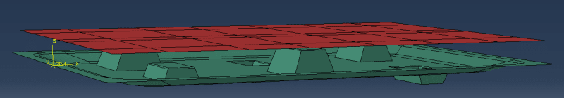
The simulation involves the Die (lower object) moving upwards until it contacts the Film (upper object). After contact is established, pressure is applied to the upper surface of the Film to conform it to the geometry of the Die.
Key aspects of the model setup include:
[ul]
[li]Materials: The Die is made of aluminum, and the Film is made of polycarbonate. Plasticity and the evolution of thermo-mechanical properties with temperature have been included for polycarbonate, with data sourced from literature.[/li]
[li]Solver: I am using a coupled temperature-displacement explicit solver, as large deformations are expected.[/li]
[li]Contact: Die-Film interaction has been modeled using a general contact approach, with a tangential penalty coefficient of 0.2. A "hard" contact is applied for normal behavior, and thermal conductance is defined to model heat exchange between the two objects.[/li]
[li]Die Constraints: The Die has been simplified as a rigid and isothermal body.[/li]
[li]Boundary Conditions: These have been set up to match the case’s physical conditions (details in the attached .inp file). Gravity has been included in the model.[/li]
[li]Temperature: The initial temperature of the film is 120ºC, while the die is at 20ºC.[/li]
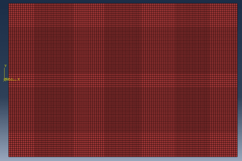
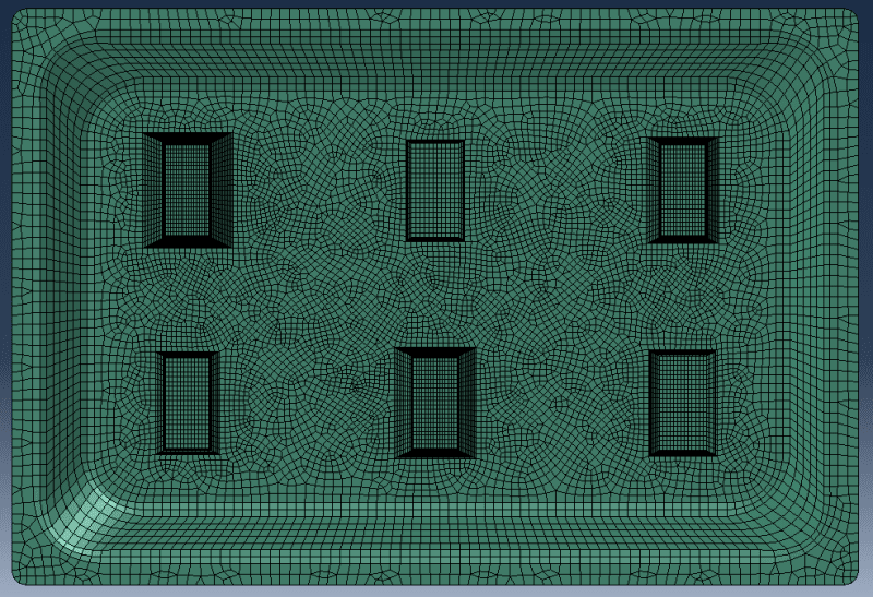
[li]Mesh: The mesh for both the die and the film is shown in the following figures: [/li]
[/ul]
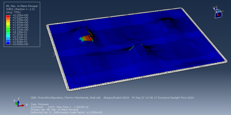
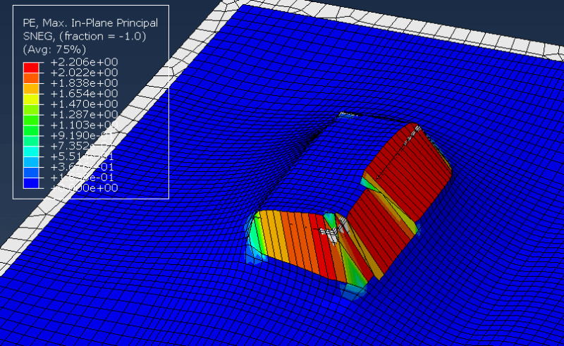
Despite these considerations, the simulation is not yielding the expected results. During the second step, when pressure is applied to the film, the deformation in certain regions becomes excessive, causing the film mesh to penetrate the die mesh. I’ve tried several adjustments, including:
[ul]
[li]Increasing the yield stress.[/li]
[li]Considering strain-rate effects.[/li]
[li]Refining the mesh.[/li]
[li]Reducing the pressure load and its application rate.[/li]
[li]Decreasing the mass scaling factor.[/li]
[/ul]
However, the issue persists. Attached are images of the deformation field and the corresponding .inp and .sta files for your reference.
 -.inp file: -.sta file:
Do you have any suggestions on how to resolve this?
Thank you for your time and assistance.
Best regards,
Rubén Navas
I am currently running a hot pressure stamping simulation in Abaqus, which is modeled as a thermo-mechanical explicit analysis. Below is an image of the assembly setup:
The simulation involves the Die (lower object) moving upwards until it contacts the Film (upper object). After contact is established, pressure is applied to the upper surface of the Film to conform it to the geometry of the Die.
Key aspects of the model setup include:
[ul]
[li]Materials: The Die is made of aluminum, and the Film is made of polycarbonate. Plasticity and the evolution of thermo-mechanical properties with temperature have been included for polycarbonate, with data sourced from literature.[/li]
[li]Solver: I am using a coupled temperature-displacement explicit solver, as large deformations are expected.[/li]
[li]Contact: Die-Film interaction has been modeled using a general contact approach, with a tangential penalty coefficient of 0.2. A "hard" contact is applied for normal behavior, and thermal conductance is defined to model heat exchange between the two objects.[/li]
[li]Die Constraints: The Die has been simplified as a rigid and isothermal body.[/li]
[li]Boundary Conditions: These have been set up to match the case’s physical conditions (details in the attached .inp file). Gravity has been included in the model.[/li]
[li]Temperature: The initial temperature of the film is 120ºC, while the die is at 20ºC.[/li]
[li]Mesh: The mesh for both the die and the film is shown in the following figures: [/li]
[/ul]
Despite these considerations, the simulation is not yielding the expected results. During the second step, when pressure is applied to the film, the deformation in certain regions becomes excessive, causing the film mesh to penetrate the die mesh. I’ve tried several adjustments, including:
[ul]
[li]Increasing the yield stress.[/li]
[li]Considering strain-rate effects.[/li]
[li]Refining the mesh.[/li]
[li]Reducing the pressure load and its application rate.[/li]
[li]Decreasing the mass scaling factor.[/li]
[/ul]
However, the issue persists. Attached are images of the deformation field and the corresponding .inp and .sta files for your reference.
Do you have any suggestions on how to resolve this?
Thank you for your time and assistance.
Best regards,
Rubén Navas