Eng-Tips is the largest engineering community on the Internet

Intelligent Work Forums for Engineering Professionals

Help on a darlington 6

Status
Not open for further replies.

LucasBS

Mechanical
Jun 4, 2010
79
0
0
BR
Despite the risk of being cast back to school, I'll ask help on this dimmer circuit for a LED strip

I have:

- MJE13003 - - 2N3904 - - 1k and 10k pots available
- Many resistors

This MJE, by my understanding, has a low gain, so I need another one to drive it (darlington).
2N3904 was the chosen, since I have a sack of a hundred
(94 now that I toasted six of them)

The LED strip, on a 12V supply, consumes 700mA. When in series with the saturated* MJE13003, the current drops to 400mA. Maybe this is expected, since the transistor has a drop of ~0.7V
*Base shorted to the 12V

But the actual problem I seek help on is on the 2N3904: it's at less than half of it's supported current (79mA Vs. 200mA), smoking almost instantaneously, and no heatsink is possible (TO92).

Here's what I have:
Darlington_uhmnyv.jpg

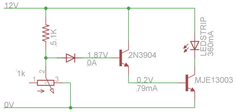
Important: this 1.87V after the diode is while floating the collector of the 2N3904. If I connect it to the 12V, the voltage after the diode goes to 5.3V, and zero current

I tried sticking the collector of the 2N3904 and the resistors AFTER the LED strip, and it doesn't heat up. But even shortening the base in this scenario doesn't drive enough current to the MJE (300mA or less)
 
Replies continue below

Recommended for you

That not a Darlington connection. Just a driver transistor configured to short the supply via the 3904 and the B-E junction of the MJE transistor.

Consider using a FET instead.
 
Would it be better with the collector of the first transistor connected to the collector of the second?
(And i still want to see a base resistor rather than the diode)
 
I would use PWM. And a FET. Much less heat.
Can the strip run off 12 V? That is not a very long strip.

Gunnar Englund
--------------------------------------
Half full - Half empty? I don't mind. It's what in it that counts.
 
As Gunnar wrote, use PWM.

Virtually 100% of commercial LED brightness control is with PWM. Even the cheapest eBay $1 (shipped) LED Strip controller.
 
"The part is rated for 0.6W, and you are attempting to to dump 2W into it?"

I didn't see that !
Or did not remember that controlling only the current was not enough

"Consider using a FET instead."

Heard FETs dissipate too much when working on a linear zone
The following would fix it:

"I would use PWM. And a FET"

Me too. I was tempted to it. But benefits aside... I'd like not to complicate things for the moment (to this unskilled guy it is). This is just half of a bigger room "automation" system. Should be quick kill.
But curious: what frequency and oscillator type would you apply here ?

The LED strip has 5 meter. Diodes grouped 3 by 3, with their respective resistors.


"And i still want to see a base resistor rather than the diode"

The 5.1k resistor was calulated for that purpose.
As the pot has a minimal resistance of 30 ohms, the voltage on the divider never reaches zero, demanding the diode to cut off.

"Would it be better with the collector of the first transistor connected to the collector of the second?"
I already attempted. Even leaving no resistor between collector and base (shortening), the current was too low to drive the MJE

But considering all the factors and suggestions, it's clear that I should go back to darlington instead of "driver"

In this configuration, the voltage on the collectors is 1V. That's probably why the current is too low on the driving transistor

I realised that a voltage divider can be put between the 12V and this driver's base
I'll report the results for those interested.

Thank you all

If nothing works, I'll buy the commercial dimmer and sell my certificate
But as this circuit is part of a larger solution, I'd like it to be integrated
 
If you connect the collectors of the driver and power transistor then you will at least have a Darlington pair. That should stop the burn-outs and allow your testing to move forward if you're determined to use a linear regulator.

I agree that PWM is probably a better solution overall, and if you do that then a FET is a good choice because the losses in the FET are typically lower than in a BJT. The advantages are more prevalent at low voltages because a BJT's saturated V[sub]CE[/sub] drop is usually larger than a FET on-state IR drop.
 
The old 555 works well, but may have "end" problems - not going fully to 0% D.C. and not quite up to 100%. Frequency? Anything above flicker limit. A hundred Hz and up.

Gunnar Englund
--------------------------------------
Half full - Half empty? I don't mind. It's what in it that counts.
 
I gave up and migrated to PWM

It works good. Only two FETs totaled on the process (that's a win [dazed])

But as predicted, there is no such a thing as 0% duty cycle, so the light never goes off
There's 1% or something close, but no zero

Kudos to whoever solves this. No idea came out of me.

I have this:
_20180809_011847_bf3bjd.jpg


Pot: 1k
Diodes: 1N4007
FET: Si2302DS

Resulting frequency is something between 500Hz and 1kHz. Well defined square wave.
But that can be reduced to fit the solution, although it will cost me a fatter capacitor or a larger pot. Both undesired
 
You bet me to it, Scotty.

But there is another way out. It will only cost you a small capacitor and it will help reducing EMI down to levels that may help you getting the product (if it is going to be one) okayed by EMC test houses.

The PWM has, as you observed, Clean and Sharp edges. That means that the current into the LED strip contains lots of HF harmonics. The original astable flip-flop, which was used Before the 555 and its cousins were available, was also named "Multivibrator" because its output was so rich in harmonics. And the 555 is richer, still, because of the optimized design.

To get rid of those harmonics, you can add a capacitor between Gate and GND. That will ramp up the gate voltage so that it never reaches turn on threshold at low duty cycles like 1% and that keeps the LED:s dark while allowing Close to full output at 99%. You will need a C that produces 1 - 10 us and that means a C like 1 nF or thereabout.

How would that help fighting EMI? Simply by reducing the di/dt in the LED chain and, since upper HF limit is proportional to di/dt, you can control the HF emission with the same capacitor.

There may be one problem; the FET will not switch as fast as before and that means some extra thermal load (stays in linear region somewhat longer). I wouldn't bother too much about that. Just try out a suitable capacitor that turns the LED:s dark at lowest D.C. and keep a finger on the FET to feel if it gets hot. And remember - hot means a lot more than 50 C, where your finger thinks it is hot.

Gunnar Englund
--------------------------------------
Half full - Half empty? I don't mind. It's what in it that counts.
 
Awesome, man

Worked perfectly. 3nF did the trick. No heating at all.

Good to know about this harmonics handling method (we all know how to get rid of noises, but some of us need a reminder sometimes)

Good to know about this SG3524 too. Although this capacitor trick is an elegant and cheap solution

Two stones with a single bird


Thank you all
 
Status
Not open for further replies.
Back
Top