Continue to Site

Eng-Tips is the largest engineering community on the Internet

Intelligent Work Forums for Engineering Professionals

  • Congratulations cowski on being selected by the Eng-Tips community for having the most helpful posts in the forums last week. Way to Go!

Help on equations necessary for staircase support bolt design (Junior Engineer) 3

Status
Not open for further replies.

Alessandro Morelli

Mechanical
Apr 27, 2022
4
Hi! My name is Aless, I am a Colombian Junior Mechatronic Engineer. I have a passion for CAD design and applied for my first job in the matter.
I got hired by a company, however, they want to test my design knowledge.
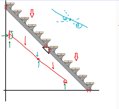
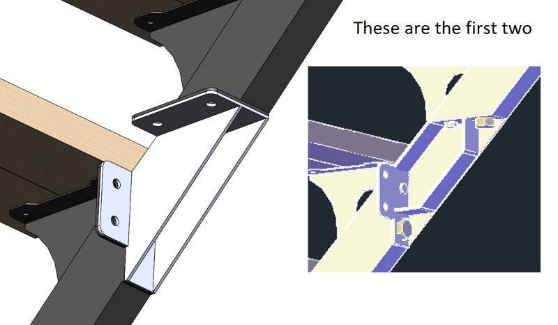
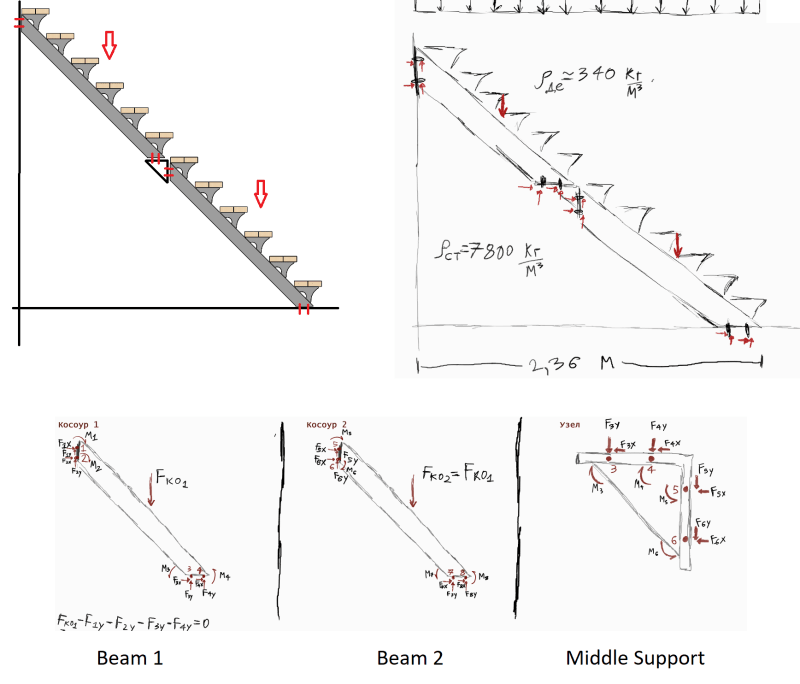
So I was given this problem of a staircase that the company produces by blocks of 6 stairs, the way they do bigger stairs is by connecting these 6 stair blocks in series by a joint in the middle using bolts (in the first image, the bolts are in the positions of the red lines drawn over the model, there are 8 of them holding the 3 pieces).
I was asked to design 4 possible variants of this joint in the 3D software, and point which bolts are under the biggest stress and give the stress numbers.
I have read the normativity, calculated dead stress and live stress on the staircase and have already calculated which distributed load the stairs should be able to withstand and under what safety factor.

Once I have the bolt forces calculated I know I will be able to calculate stress and design variants in no time, however, the knowledge of how to find the forces in the first place escapes my memory.
They are implying this is a very simple calculation that is done by an experienced engineer in under 2 hours by hand and they won't allow me to use the software's built-in finite element analysis tool
Perhaps I just don't know which equations should be used in the first place.
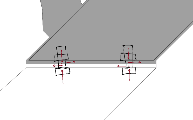
I have tried free force diagram by separating the distributed load into 2 punctual forces (Fko1 and Fko2) and calculating for the 3 parts but it gives me a system of 16 equations and 16 variables (forces in X and Y for 8 bolts), which I doubt can be done in so little time by hand and no matrix calculator.
I have also looked into Bolt Group Calculations using the elastic method, however, the books I found only go as deep as having only one set of fixed grouped bolts on one side.
I would be forever thankful if there is an experienced engineer in the matter that could simply tell me which equations might be of interest to me in this case.
Or even a book I could look into.
I already know how to use the 3D software for design and simulation, I think that once I understand this calculation I will be able to do a great job at the company, if I manage to keep it...
Thanks a lot for reading and for the invaluable help, and have a nice day!
aaaa_v79lk2.png
 
Replies continue below

Recommended for you

Wouldn't it be easier for OP if the free body diagram is a propped cantilever with internal hinge (statically determinate)?
Stair_c92oyj.png

The far left end being fixed, middle as hinge, and far right-bottom as roller. With the moment at the fixed end you can compute the stresses and shear in your bolt. The internal loadings developed at the hinge being used to check the stresses of the bolt at the hinge.
I personally think that's a start.
 
From where I'm sitting, the main issue with the propped cantilever is, what are you framing in to on the wall? I'd set it to shear and tension, and leave the bottom as the roller (I've found most EOR's get a bit fussy when you tell them you need to apply any horiz. shear into their floor slab). Then, do the moment connection through the piece that you have control over (the splice).
 
Bulb - it's probably unlikely that the end condition will behave as a fixed connection (though I don't know-it's possible), and I don't think you can sell the roller at the floor at all. It certainly won't behave that way.

Easiest is probably pinned ends, check it as a single member. Then solve for the internal shears and moments at the splice to determine loads/stresses in connecting elements.
 
I thought OP has to come with 4 different possibilities.

The fixed end is quite uncertain but the roller makes it determinate and easier to analyse in this scenario (if it is fixed). I agree it won't behave that way at the floor.
The pinned ends is absolutely the easiest. I guess OP would need to be able to justify his/her reasons for his/her free body diagram for all other alternatives.
 
I read all the documentation.
I now know why you guys choose these joint types to try and make it statically determinate and when you calculate moments and forces according to a simple beam.
However, there are some things I struggle to apply here.
The first thing is that they are all bolts, they effectively act as fixed. All of them.
I have no choice in this, I simply design variants of the SHAPE of the middle piece, that's it.

human909 said:
Add back in the loads parallel to the stairway beam.
I tried your method too...
But the stair pieces are already designed to have 2 bolts on each joint, that makes it 8 bolts in total, each one is a little red line in my original drawing. Check the image of a middle piece I designed, you see? 2 on each side, and then 2 more on stairs to wall and 2 on stairs to floor, 8 total.
So, such a system is not only indeterminate but indeterminate to the 6th degree. Now, as phamENG pointed out, some choices for the joints would kinda act like it does in real life, some would be too far away.

phamENG said:
Easiest is probably pinned ends, check it as a single member.
In fact, if I assume all 8 to act like pinned ends, yes, it is determinate...but these are bolts, which WOULD apply a momentum reaction that I would have to take into account when designing the joint.

Here are some examples of the middle piece that I did.
%D0%A1%D0%BD%D0%B8%D0%BC%D0%BE%D0%BA_nskkbz.png


That said...is it safe to assume, when I have calculated all of them that I will be able to simply input the resultant forces on the bolt design equations as this next image shows to calculate tensile and shear stress and that would be approximately ok? Or is more needed?
333_w46dst.png


Once again thanks for all the help guys, it has been invaluable.
 
1) assume LH support is simple (not cantilever), then bolts are carrying shear only. Sure the joint can carry "some" moment (if you say fixed then people jump down your throat "there ain't no such thing"), but small in the scheme of things.

2) the middle joint fitting can carry some moment ... will the two stairs deflect as one integral piece or can you think of them as bending separately, as two distinct pieces no, you can't. Then it's either ...
a) analyze as a single beam, extract the shear and moment at the joint and determine the fastener loads, or
b) analysis each piece as a beam, simply supported. The trick here is to catch that the reaction from the upper beam is applied as a load to the lower, and vis a versa. well, that was dumb ... the middle can't be a joint, needs to react bending ... sigh

In both cases draw a FBD, and see the external reactions are the same.

another day in paradise, or is paradise one day closer ?
 
Alessandro Morelli said:
The first thing is that they are all bolts, they effectively act as fixed. All of them.
I have no choice in this, I simply design variants of the SHAPE of the middle piece, that's it.
Just because they are bolts doesn't mean they are fixed. But if you insist on assuming all joints are fixed then I have an answer for that and it is at the bottom. Though read the rest to understand it all.

Alessandro Morelli said:
But the stair pieces are already designed to have 2 bolts on each joint, that makes it 8 bolts in total, each one is a little red line in my original drawing. Check the image of a middle piece I designed, you see? 2 on each side, and then 2 more on stairs to wall and 2 on stairs to floor, 8 total.
So, such a system is not only indeterminate but indeterminate to the 6th degree. Now, as phamENG pointed out, some choices for the joints would kinda act like it does in real life, some would be too far away.
You are over complicating things.

At the start forget about working out the reactions at the bolts themselves. See step 3 in my recipe. Treat the whole set of stairs as ONE beam with 2 supports. The entire problem becomes simple. Lets pick pinned supports at the ends so that they are simply supported. Lets consider the force acting the the perpendicular direction only as 'w' which is w=W/[√2] for a 45 degree stair.

I know that for a simply supported beam the maximum moment occurs in the middle with zero shear:
M=wL^2/8.

BeamBendingTable1_sh9mmw.gif


With that information you have all you need to calculated the forces on the bolts in the middle.

At the middle you have two joints both carrying the full moment of 'M'. To calculate forces on the bolts you can assume the moment acts over the distance 'd' between the bolts and it is just:
M/d to give the tension force on 1 bolt in the joint. The other bolt carries no tension or compression the opposing compression is take by the bearing surface. So in total 2 bolts with M/d tension and 2 bolts with ZERO load.

You now have all the forces in all the bolts in the middle.

What about the ends? We have assumed simply supported so equal shear both sides. So WL/2 or wL/2 horizontally and wL/2 vertically. From inspection I see that the top bolts are in shear in the vertical direction so each bolt carries wL/4 and the bottom bolts are in shear horizontally (assuming no friction) with each bolt carrying wL/4.

You now have all the forces in all the bolts in the ends.

QED

You have solved the problem.

(I think that is all coherent and correct for the given assumptions. Normally I hate giving away full answers for questions like yours but today I felt the need to do the mental gymnastics myself, as I too am often reliant on computers too much.)

**Note by assuming simply supported ends you are making your the calculations a little easier but you are also increasing the loads on the middle bolts. You will find some fairly high forces in the centre bolts. If you assume fixed ends and centre then you will get lower forces in the middle bolts but the computation becomes slightly but not significantlyy more complicated. Shear stays the same, moment reduces in the middle to M=wL^2/24 and increase at the ends M=wL^2/12. The same procedure applies.
 
Status
Not open for further replies.

Part and Inventory Search

Sponsor