Continue to Site

Eng-Tips is the largest engineering community on the Internet

Intelligent Work Forums for Engineering Professionals

  • Congratulations waross on being selected by the Eng-Tips community for having the most helpful posts in the forums last week. Way to Go!

Help Pipe Support Engineer with Moment Connections

NickDePinhoPE

Mechanical
Sep 27, 2024
2
Looking for some help on how to design the connections in this scenario. In this example shown I have an axial force of say 100lbs per each pipe. I need to design connections between my horizontal HSS and the building Ibeams.
How would I go about doing this? Typical I used unstiffened seated connections for deadweight loads. Any help or calculator I could use for this would be really helpful. I work with pipe supports I do not really need any information on connections that is beyond this scenario.
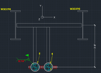
1737489391902.png
 
Replies continue below

Recommended for you

You could put in some bracing to take the axial load out. That would save you from moment connection design.

Side note: I usually see the HSS beam located at the bottom flange of the W30 and typically an angle is used. You probably have your reasons for the design. Just wanted to throw that out there.
 
How much axial movement can the pipes tolerate?
 
you may need two horizontal HSS beams along with matching V shaped vertical connectors to take care of the axial loads.
 
I have an axial force of say 100lbs per each pipe. I need to design connections between my horizontal HSS and the building Ibeams.
How would I go about doing this? Typical I used unstiffened seated connections for deadweight loads
You did not provide a lot of info . here.. Regarding the axial load , are these horizontal loads along the pipes ? Can you shift the pipes to hang directly under one of the WF?
If the load along the pipes , the bending resistance of hangers and torsional resistance of the horizontal HSS would be negligible and you are expected to provide some bracing.( i.e. a diagonal element btw pipe clamp and another horizontal beam .
Pls provide more info. to get better responds.
 
So without doing any math, I would make a few changes.

First, I would opt for a trapeze off the bottom of the W beams. That way you go direct into your moment connection on the flange of the W beam without a torsion bar in the middle.

Second, I would opt for limit stops, u-bolts with limit stops, anchored shoes, or some other means of anchoring the pipe to the steel. I can't tell if your picture is implying welding the clamps to the pipe or just welding the stanchion to the pipe, but either way that is less preferable. Don't weld "removable" hardware to a pipe and a stanchion that long is just asking for issues (or requiring repads, etc.). And if you truly need an axial limit, don't depend on friction if you can help it.
 
Assuming by axial load you mean into the page, and therefore the HSS between your W-beams is actually in torsion, I'd bet if you just weld it all the way around to the web of the W-beams that you'd have much more capacity than you need. If you put 1 1/2" of 5/16" weld on only the top and bottom face of the hss to the W-beam, that's a good amount of torsional resistance, in excess of 1200 ft-lbs. When in fact you'd have it on all 4 sides, all contributing to the torsional moment transfer. Your demand is something like 750 ft-lbs of torsional moment from the two pipes combined.
 
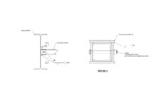
Here's a sketch of your most conservative connection design option.

A 4-plate end "sleeve" w' long slots that's field welded to the HSS (also long slots) & W30 support. This lets you 1) push the "sleeve" inward, 2) swing the HSS system into place between the W30 supports, 3) extend the "sleeve" to the W30 faces, 4) field weld the "sleeve"-to-W30 support, then 5) field weld the HSS to the "sleeve". This is used in nuclear jobs quite a bit, for larger supports.
Fun Little Sketch.jpg
 

Part and Inventory Search

Sponsor