Continue to Site

Eng-Tips is the largest engineering community on the Internet

Intelligent Work Forums for Engineering Professionals

  • Congratulations KootK on being selected by the Eng-Tips community for having the most helpful posts in the forums last week. Way to Go!

Help please with Control Flow Valve + Ultrasonic Meter AGA 9

Status
Not open for further replies.

Cesar Almada

Mechanical
Nov 9, 2020
23
Hi everyone

I have a question about if I have a Control flow valve and after I have your ultrasonic meter in a process of natural gas.

A transporter of natural gas told us that if we have that configuration it's possible that poor measurement occur.

I don't know if it's right, because i designed my meter package with AGA 9 and i respected the distances between spools.

I attach the drawing of my package of control flow and meter, if you can help me how can i explain that is unnecessary to change my packages between them and how being right now its okay.
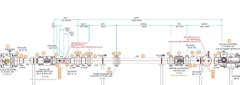
Captura_i1nxkf.jpg
 
Replies continue below

Recommended for you

He is likely concerned about turbulence/flow maldistributions induced by a partially-open control valve flowing downstream into the meter. Can you reverse the positions of meter and valve (put meter upstream of control valve)? If not, look into a flow conditioning element (baffle tube array, or multi-orifice plate) between valve and meter. The manufacturer of the meter should be able to give suggestions.
 
Betrue and your meter man are correct. Control valves should always go in downstream of a metering device. If upstream, they must be well away from the meter skid and you should probably include straightening vane or tube bundle. The closer to laminar flow the better. AGA guideline barely includes enough length for a 90°elbow. All valves near a meter should be full bore and either full open or full closed, never partially open. The pipe just before the meter should have a machined finish. Even a close elbow would need the straightening tubes.

 
Thank you for your answers.

I can't move mis package between them because everything is built. I only have the conditioner that is neccesary like AGA 9 says, betwen first and second spool, upstream of meter.

So i need to answer that the control flow valve doesn't affect the measurement, but i don't know how to do. I told them that my meter package is in rule with AGA 9 and AGA 9 dosen't say nothing about control flow valves.

Do you know if in some part of AGA 9 say something about that?
 
Been awhile since I've read it, but I dont think it says anything specific about CVs. I have always put CV downstream because we never wanted some other downstream company potentially controlling the pressure in our meters by default. It also just happens to be the best place for accurate metering as well, so everyone was happy.

 
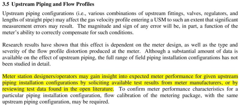
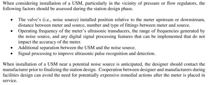
There's 'hedging' language in AGA 9 2017 about control valves.

- 3.5 Upstream Piping and Flow Profiles
section_3.5_upstream_downstream_piping_ppfebg.jpg


- 3.6 Acoustic Noise
section_3.6_Acoustic_noise_vj9qgd.jpg


that indicates to me that the AGA 9 layout is not a cookie-cutter design template.
 
Definitely not a cookie cutter. I dont recall anything more than upstream straight length being specified and that might have actually been mentioned in the Daniels installation guide of the day.

 
The sentence immediately following danw's highlighted text block is the one you should focus on, given your apparent constraints - i.e. find a way to calibrate the meter (compare to a known good meter).
 
That's going to be difficult. I've never seen one with a CV attached directly to the upstream flange like that. A full bore ball valve, yes. But not a CV. CVs are usually at a separate location at least 5m away from a meter skid. There is basically no way that arrangement will work. I would have to reject it no matter what some calibration showed. In fact I'd reject it even faster if someone even tried that stunt.

 
"For optimal flow measurement conditions, manufacuturer suggests the piping configurations
below. Regardless of the configuration selected, the user agrees to accept full
responsibility for the site piping design and installation.

Flow conditioning is recommended for best measurement results"

With flow conditioner minimum 8D to 10D upstream, 3D-5D downstream


Still that doesn't exactly say that a control valve 10D upstream is OK. Like I said, with 8 to 10D, upstream you could put a full bore flange, or full bore valve, or straightening vanes, which is what you'd need if you had an elbow in front of that. CVs are best left for an additional 20D or more. The higher the relative pressure drop, the farther the distance away. You really want to put other fittings and devices that are not full bore, or have directional changes (filters, elbows, tees etc.) as far upstream as their equivalent friction length.

 
1505, agreed, but like the OP indicated it is already built, and per your experience and mine, he should have considered asking questions prior to spec/purchase. According to the OP description, the meter cannot be used for custody transfer.

Some of the multipath ultrasonics are priceless, and require special considerations.

 
Right. I guess the problem is exactly that AGA9 is for custody transfer, but the present configuration is a poor way to do it.

It would be great if the CV could be relocated somewhere downstream. Expensive, but probably necessary. A full open CV that close is likely to have adverse effects even if pressure and flow are actually controlled elsewhere.

 
It's all class 600 in a straight spool.

Just shuffle the bits around.

Ultrasonic meters are great but can be sensitive to fluid vortexes etc.
Codes can only do so much. Sometimes you need to read the vendors guidance and try and follow it.

It's very easy to move all the bits to put the meter upstream the CV.

What's the problem here?

Remember - More details = better answers
Also: If you get a response it's polite to respond to it.
 
I figured there was something blocking further thought about that. Maybe pipe supports, foundation constraints, rerunning instrument and control lines, etc. But when push comes to shove, shifting left and relocating the CV downstream would be a slightly better configuration. Still no guarantees. But they might have to try it.

 
The control valve is 20D up stream, the flow conditioner 10D upstream, temp meas approx 3D down stream, that is per manufacturers requirements, Caesar your installation is fine
 
Wait to see the cheque clear.

Caesar, I do wish you luck. It may work. I just have doubts.

 
Whether or not it is an acceptable configuration depends on the purpose of the flow element. If it is only used for control , then it may be fine as is. If it is a legal "custody meter" for purpose of determining the cost of consumed gas or the efficiency of the process then it will not meet the requirements for accuracy.

"...when logic, and proportion, have fallen, sloppy dead..." Grace Slick
 
AGA 9 was specifically written for ultrasonic custody measurement in natgas treasmission systems, which is why this is a problem. Internal bore diameter is specified to the mil, amongst other strict requirements. It will have to survive a calibrated full range flow test.

 
Status
Not open for further replies.

Part and Inventory Search

Sponsor