Eng-Tips is the largest engineering community on the Internet

Intelligent Work Forums for Engineering Professionals

Help W/ Risa Model 2

Status
Not open for further replies.

Revv

Structural
Aug 23, 2021
87
0
0
US
Hey Guys,

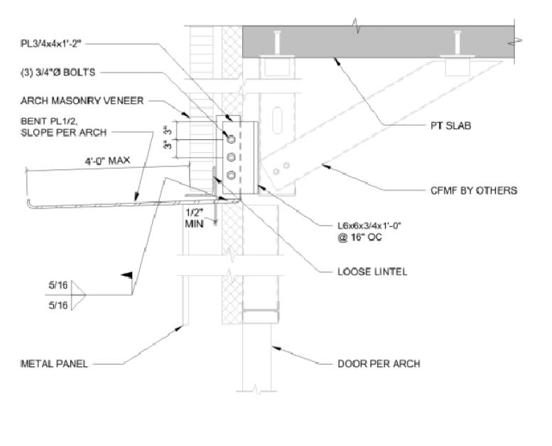
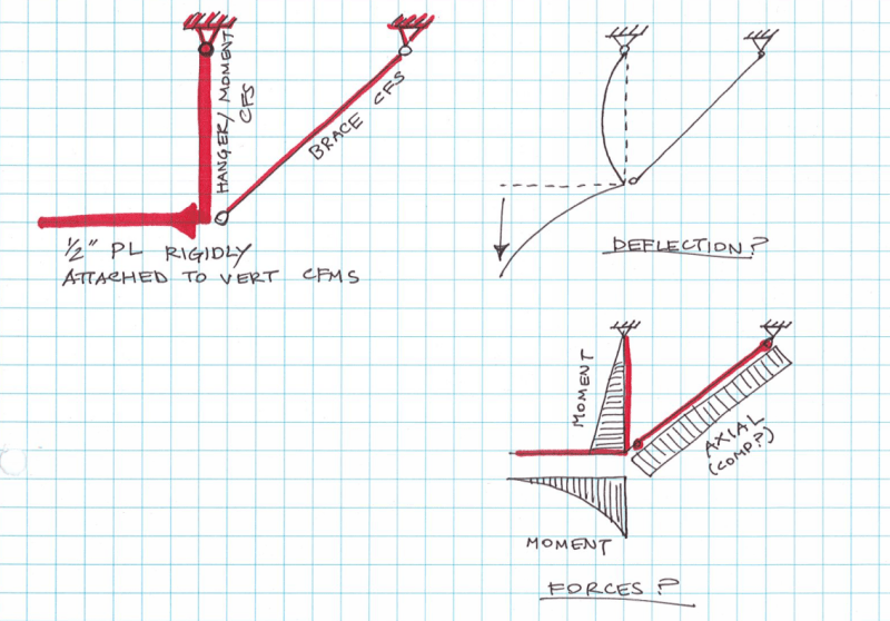
Attached is a detail I'm trying to put into Risa along with the model I've drawn for it. I would like to get some input on how it looks as I'm not super familiar with RISA as a whole. Am I right to have a rotational boundary condition at N1? It seems to be the only way to get instability out of the model. Do you guys have other ideas what would cause this instability/how to fix it?

So Tldr: is my Risa model reflecting the condition well(correct boundary conditions at correct locations) especially at N1 where I had to add a rotational boundary condition and if not what should be done to prevent instability?
 
 https://files.engineering.com/getfile.aspx?folder=301ef185-8d07-4ed2-aceb-61c6319b6694&file=Capture1.PNG
Replies continue below

Recommended for you

The model looks like you have a beam supported at a single point by two tension elements. This would be inherently unstable.

Based on your drawing of the structure, I think the vertical member should NOT have pinned connection at the bottom (i.e. where it connect to M1).
 
I am late to this post but better late than never.

That 1/2" plate, is it a canopy? Also, as a side note that has nothing to do with the RISA model, did you ever try to bend a 1/2" plate to create the lip at the end? I suggest that you consider changing the plate thickness unless driven by design. Keep in mind that 1/2" plate weighs = 40.8*0.5 = 20.4 psf. That is heavier than an industrial roof system (joist, deck, insulation, and MODBIT roof membrane that consists of base sheet, intermediate sheet and cap sheet)!  


Regards,
Lutfi
 
Your structural concept is not clear. Where are the supports for the PT slab? Is the 1/2" thick cantilever plate and assembly suspended from the slab? Or is there a line of columns and beams inside the wall?

Capture_dud1dq.jpg


Until you have developed a structural concept, forget about Risa or any other software.
 
Just looking at your detail and your model, it is apparent you need help from an experienced engineer. Do you have a mentor you can discuss this with?
 
It would be helpful to see a floor framing plan. If there are columns supporting the left edge of the PT slab, they could be designed to resist the moment from the 1/2" cantilever plate; however the mixture of steel support and post tension slab seems bizarre. So does the cantilever plate.

 
Member N1 N2 shouldn't have a release at its N1 end if you're transferring bending into it from your PL beam element. Just remove its end release to no releases at its bottom end.

I'd expect it to behave something like this...
Screenshot_2023-07-17_171053_kelk5m.png


Not so sure about cold form taking this though. I would also say weld your PL3/4x4x14 to your L6 to have an moment connection, and use bolts just as erection aids. Could use SC bolts to transfer moment too... Huuuge eccentricity.

Id recommend modeling the PL as shells to see its true deflections, since this 2D analysis assumes the plate is continuously supported along its edge, though its (Im assuming) only supported at ever stud.
 
I agree with NRam's analysis. I don't like the fact that the steel assembly is hanging from the underside of the PT slab. That requires overhead welding. The PL3/4x4x1'-2 should be shop welded to the cantilever plate at the required spacing, then the assembly can be lifted and bolted to the assembly suspended from the PT slab.

It really is a terrible detail; hopefully a better detail can be found.
 
Status
Not open for further replies.
Back
Top