Continue to Site

Eng-Tips is the largest engineering community on the Internet

Intelligent Work Forums for Engineering Professionals

  • Congratulations SSS148 on being selected by the Eng-Tips community for having the most helpful posts in the forums last week. Way to Go!

Help with a steel connection! 1

Status
Not open for further replies.

NAFTALI-HAKOHEN

Civil/Environmental
Apr 8, 2021
26
Hi all,

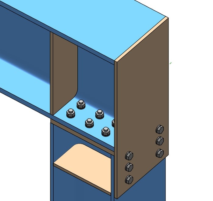
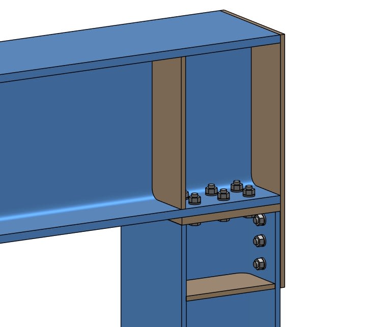
just wondering if attatched connection is a moment connection, as beam flange
is welded at top flange to a steel plate thats bolted to column flange.

what the weakest point of this connection and whats the main checks i need to do?

any tips for good programs to model and check steel connections in?

thanks

(first post !)

CON2_b7fdng.jpg


CON1_oycpaj.jpg
 
Replies continue below

Recommended for you

1) I wouldn't consider it a moment connection. Sure, it will transfer some small moment, but I don't see anything that's going to prevent rotation of the beam.
2) Unless you have some VERY strange existing structure you're working on, I would not submit that connection.
3) Ask a fellow employee about this.
4) Steel connection design of this level doesn't require sophisticated software, until you get into complex geometry requiring FEA.
5) The best way to check your steel connections is to hand the concept and calculations to the grey-haired man who's been with the company for 15 years. You know the one.

 
If you turn this 90° it looks vaguely like a combination of a flush end plate connection and a bolted flange plate. I would say it definitely has some moment capacity, but maybe not alot. If I had to calculate a capacity I would probably start with a flush end plate connection similar to AISC Design Guide 16 (turned 90°) to get me in the ballpark.

All that being said, unless you have some unique circumstances I would not re-invent the wheel when it comes to moment connections. There are a variety of resources available for some of the more common connection types.
 
It can develope a fair moment... and more if you extend the top plate to the inside and add bolts at that location... The 12 bolts inside the web is a bit of overkill and there are better ways of using them. I'd use SMath or Excel or something of that ilk...

Rather than think climate change and the corona virus as science, think of it as the wrath of God. Feel any better?

-Dik
 
1) For closing moments, this is a great moment connection and could be designed using conventional methods for bolted moment connections.

2) For opening moments, I agree with RWW0002 that it resembles an flush end plate moment connection. I'd modify that to assume a center of rotation about the outer column flange however as I expect that is how it would work.

3) I see no purpose for your lower stiffener and would delete that.
 
RWW0002 said:
If you turn this 90° it looks vaguely like a combination of a flush end plate connection and a bolted flange plate. I would say it definitely has some moment capacity, but maybe not alot. If I had to calculate a capacity I would probably start with a flush end plate connection similar to AISC Design Guide 16 (turned 90°) to get me in the ballpark.

I totally agree, this is a cross between a flush end plate and a bolted flange plate. Personally, I don't agree with Dr. ZoidberWoop. It looks like a pretty good (though atypical) moment connection to me.

Here's how I would design it:

1) Flange plate in tension: design that flange plate the way you would any flange plate in tension.
2) Flange plate in compression: design the flush end plate the way you would for any flush end plate.

Now, I believe flush end plates are considered PR (partially restrained) rather than FR (Fully Restrained). So, there is some basis for saying that it's more flexible than many standard moment connections. But, I suspect part of the reason it's this way is that you don't want any field welding. Is that correct?
 
Why partially restrained?

Rather than think climate change and the corona virus as science, think of it as the wrath of God. Feel any better?

-Dik
 
hi,

the beam is going to support an existing slab with a large point load that were worried about punching failure,

so its designed for a closing moment,

to resist the top flange of beam moving up, the bolts in end plate should resist this via shear , and bottom flange of beam will compress inner flange of column, so i see a pair of forces to provide the moment resistance im looking for,

kookt, why u assume center of rotation about outer col flange? surely the point of hinge is on inner column flange?

with the beam sitting snug on the columns this connection 'seems' solid to me, not sure why its not so conventional?

thanks
 
OP said:
kookt, why u assume center of rotation about outer col flange?

I made that statement in the context of discussing opening moment behavior. It would not apply to closing moments.

OP said:
with the beam sitting snug on the columns this connection 'seems' solid to me, not sure why its not so conventional?

I would guess that's because most moment connections:

1) are designed for revering moments and, in those cases, your detail would have disadvantages.

2) A lot of multi-story moment frames have the columns more than one story tall.
 
Status
Not open for further replies.

Part and Inventory Search

Sponsor