Continue to Site

Eng-Tips is the largest engineering community on the Internet

Intelligent Work Forums for Engineering Professionals

  • Congratulations GregLocock on being selected by the Eng-Tips community for having the most helpful posts in the forums last week. Way to Go!

help with blends 2

Status
Not open for further replies.

sukangook

Mechanical
Feb 18, 2020
5
Hello, everyone! New to the forum, but have been reading many useful things here.

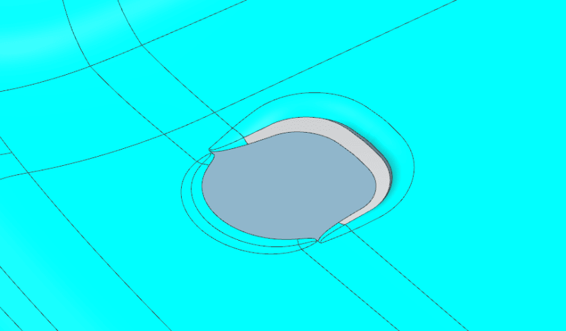
I have a problem doing blend that transition from concave to convex or vice versa.
I have attached the image and parasolid file.
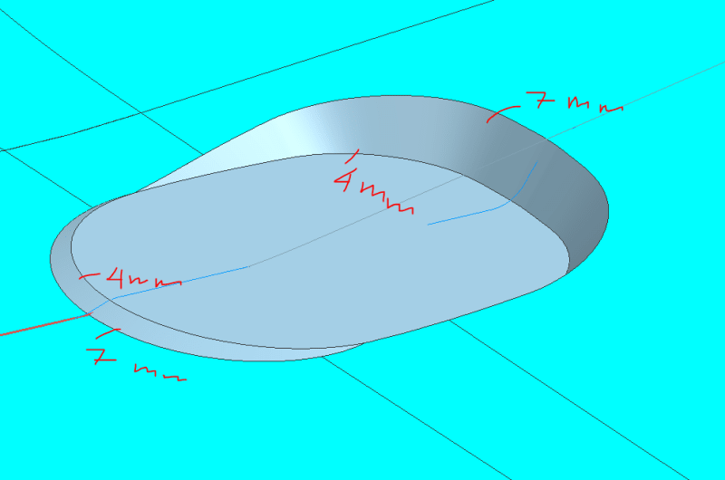
%E3%82%AD%E3%83%A3%E3%83%97%E3%83%81%E3%83%A3_pwdqts.png

I could make the blend if it is the same radius and less than 2mm. But that is not what I need. What I need can be seen from the image.

Also, any tips on doing blends such as this for future reference? I am new to NX and am having a hard time doing blends.
Any help is appreciated, thank you so much!
 
Replies continue below

Recommended for you

I am using NX11. Sorry, forgot to mention it before.
 
blend_pykd0c.png


Theres something wrong with that back wall surface.

When I blend in this order according to picture from left to right.
7mm then 4mm
then the 7mm and 4mm from right to left. the 4mm only partially shows up.
When I export that to an NX11 compatible X_T it blows up


edit forgot picture
 
difficult case.
I am on NX12 so i can't share the model.
I did not succeed applying the blends as you require, but i played around with a slightly different shape, avoiding that tricky 4-edge vertex.
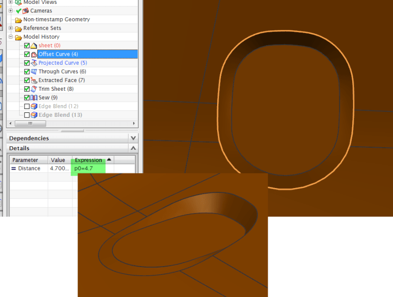
I created a offset curve from the planar face "inside", that "happened" to be 4.7 by quickly comparing to the upper outline.
then i projected that to the outer faces, normal direction from "inside face".
I created a Through curves sheet between edges of "inside face" and projected curve. ( alignment by points, output =sheet.)
trimmed and sewed etc.
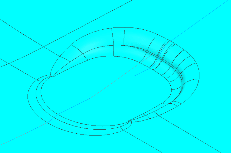
this is how it looks without the blends. Blend r=7 and r=4 no problem.

What do you think ?
( I do not know the purpose of this model so i don't know if this modification is ok or not.)

Regards,
Tomas
2020-02-18_19-58-03_iwowys.png
 
robnewcomb,
I also noticed that, I don't know why though. I made that back wall with law extension and then did an offset.
Checked it with examine geometry and didn't find anything wrong.
Made a new one with extrusion and draft instead of law extension and was able to made this:

%E3%82%AD%E3%83%A3%E3%83%97%E3%83%81%E3%83%A31_cjczrw.png


Tomas,
I tried to recreate your solution. that is a very elegant and clean solution, I like it.
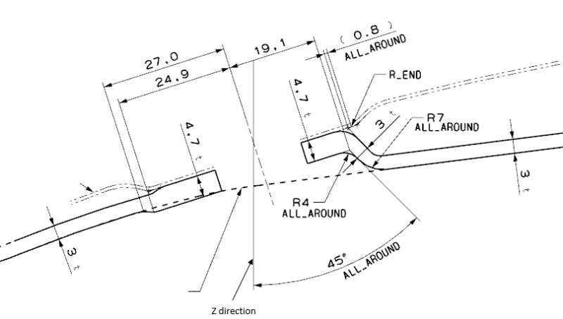
However, I don't think it meet the needed requirement. It is a practice problem that I got and I need to make it according to:

%E3%82%AD%E3%83%A3%E3%83%97%E3%83%81%E3%83%A3_qibbfh.png


Thank you so much for the responses!
 
Sukangook said:
It is a practice problem that I got and I need to make it according to

Please read the forum posting guidelines...

PostingRules_ufnegx.png


Ronald van den Broek
Senior Application Engineer
Winterthur Gas & Diesel Ltd
NX9 / TC10.1.2

Building new PLM environment from Scratch using NX12 / TC11
 
Oh, sorry about that.

Just to clarify, I am not a student and this is not a coursework or thesis.
It was a model that was given to me to practice my NX skill by my company. I already did it several times before I post it here.
The results I got was inconsistent, depending on how I did it so I just want to know how others would approach this problem.

I think this is not againt the policies, but I am sorry if it is.
Thank you!
 
sukangook said:
I think this is not againt the policies, but I am sorry if it is.

In your case it isn't :)


Ronald van den Broek
Senior Application Engineer
Winterthur Gas & Diesel Ltd
NX9 / TC10.1.2

Building new PLM environment from Scratch using NX12 / TC11
 
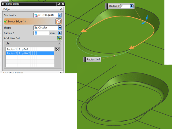
If i adjust the sizes slightly , instead of r= 7 and 4 ; I use 7 and 2. I can do the solution seen below.
Blend 1, two different radii ( this can be done as separate blends as well.) Note both are concave.
2020-02-21_16-30-33_plgaxo.png

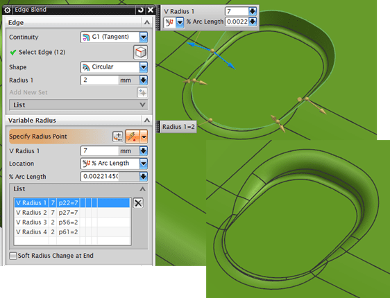
Blend 2, because of the previous blend, concave-concave, I get a tangent continuous edge all around.
this then requires a variable blend, 7-2-2-7mm ( Any order)

2020-02-21_16-38-40_z872gj.png


This is not according to the specs of radii 4 and 7 but the shape is since that "typical 2D-drawing view", doesn't state how the transition between the different radii should look.

Regards,
Tomas
 
The diemaker is just going to ball it all off anyways... [evil]
 
Tomas,
Interesting take on it. Did not think to make the edges tangent continuous before.
I will keep it in mind, in case I face similar problem in the future.

Thank you so much for the responses! Learned so much from this forum.
 
Status
Not open for further replies.

Part and Inventory Search

Sponsor