Continue to Site

Eng-Tips is the largest engineering community on the Internet

Intelligent Work Forums for Engineering Professionals

  • Congratulations waross on being selected by the Eng-Tips community for having the most helpful posts in the forums last week. Way to Go!

Help with FEA Verification 2

Status
Not open for further replies.

Burner2k

Aerospace
Jun 13, 2015
193
Hello,
I am looking to some help (references) about verification of FEA methodology.
Specifically for transient dynamic analysis. I am thinking of a simple tensile load or pointed transverse load
on cantilever as shown below. I will first try with axial since it will be a single DOF system & hence easier to do hand calcs.
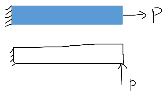
Screenshot_20240427_145243_vb5zup.png


The force will be a function of time as shown below.
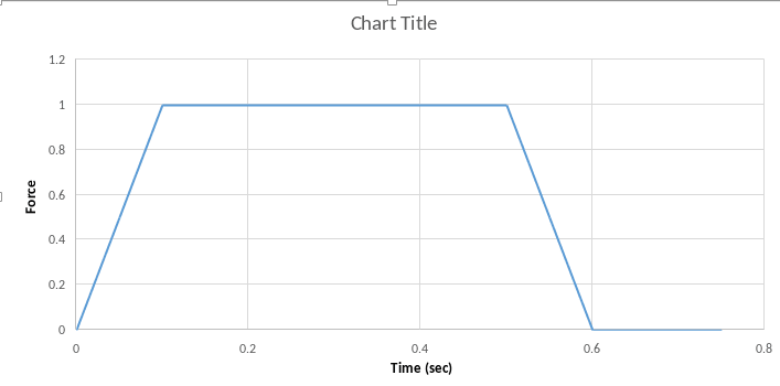
Screenshot_20240427_145411_tz9qgr.png


I am hoping to correlate FEA output with hand calculations. I am not sure if hand calculations can be even
performed for the above. If yes, I would appreciate some help on where I can find relevant formulas. Basic idea is to figure out I've got the methodology right.
 
Replies continue below

Recommended for you

Check the book "Formulas for Dynamics, Acoustics and Vibration" by Blevins. It's like Roark's for dynamic problems.
 
... and to quickly answer your question, yes definitive hand calculation solutions exist for those simple cases. You could also code a series of spring/mass systems to do it numerically. There is also the hilarious Rayleigh Ritz approach, although that gets rather hairy for higher order modes.

Cheers

Greg Locock


New here? Try reading these, they might help FAQ731-376
 
Thanks for the replies. I have asked my company to purchase Blevins. In the meanwhile, I did run a small test case and I got results which just confused me more. I have to admit that my understanding of Dynamic systems is evolving.

I hope the images are clear enough. Please help me out in getting a better understanding.

01_xjpi5o.png


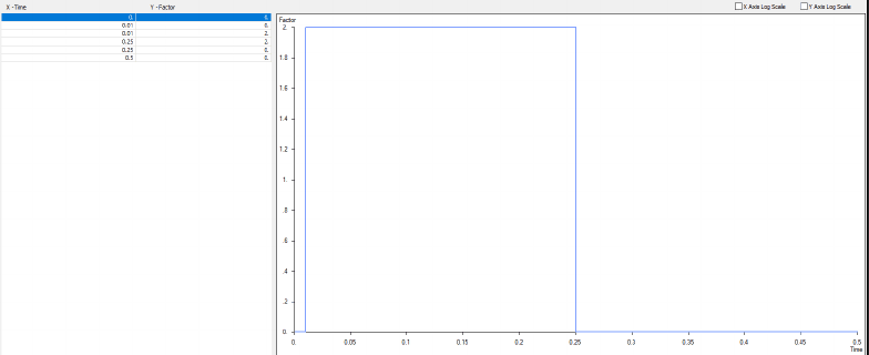
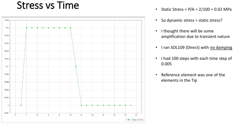
The loading is a step function with a factor of 2
02_bgq3yy.png


03_ny1bvi.png


04_itcqa7.png
 
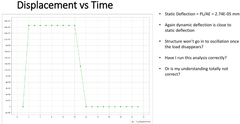
Unfortunately I can't read the numbers on your graphs.

To see the dynamics of that system you'd need to be running a much smaller timestep, of the order of 1E-6 or smaller

Cheers

Greg Locock


New here? Try reading these, they might help FAQ731-376
 
Burner2k
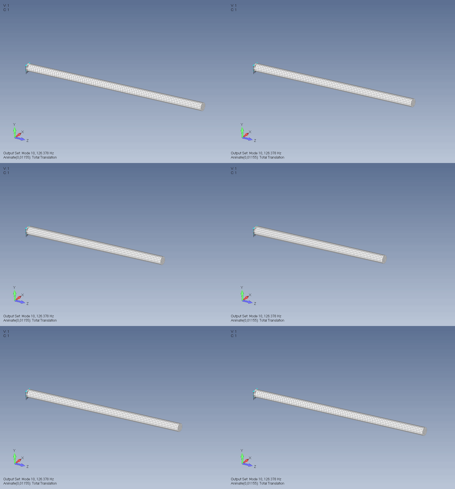
All dynamics begin with Normal Modes. Run normal modes and find first frequency(lambda) of mode that represent rod movement in axial direction.
Rod_hdqgaw.gif


Now if you want to observe some transient behavior you should apply load at duration with same order as one period of oscillation (T=1/lambda) of rod axial mode. To capture transient behavior you should use timestep not greater than 1/12*T or 1/20*T. Think of it as you have one sine wave with period T and you need some number of points to capture it. So 6 points per half sine wave is bare minimum.

Otherwise your load period is greater than period of first axial mode so structure response to it like to static load.
 
That's one approach. The other is that the axial speed of vibration is 7000 m/s and the thing is 0.1m long.


Cheers

Greg Locock


New here? Try reading these, they might help FAQ731-376
 
Firstly, I apologize for the numbers not showing up big enough to be read.

Secondly, thanks GregLocock & karachun for your replies.

Karachun, I followed your suggestions.

I ran SOL 103 Normal modes analysis and the corresponding frequency for which axial mode gets excited is 12900 Hz

T = 1/Lambda = 1/12,900 = 7.75194E-05 sec

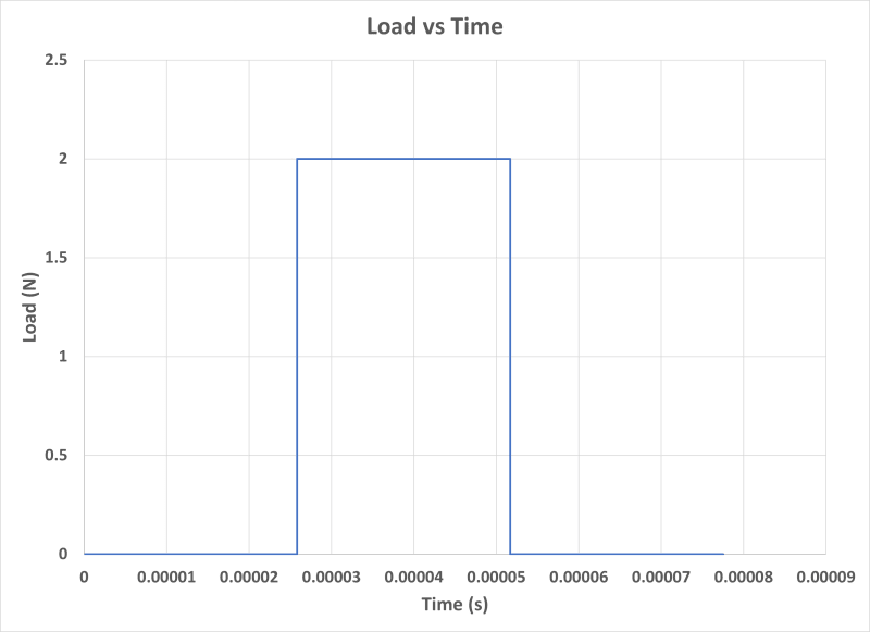
I created a loading function as follows:

Time(s) Load(N)
0 0
2.58398E-05 0
2.58398E-05 2
5.16796E-05 2
5.16796E-05 0
7.75194E-05 0

Here is a plot of Load vs Time:

Picture1_oj9czz.png


Now for total number of steps, I used what Karachun had mentioned i.e. 1/(12*T) = 1/(12*7.752E-05) = 1075 steps.

The time increment between each step = 7.76E-05/1075 = 7.21111E-08 sec.

I wanted to solver to output at an interval of 50 cases.

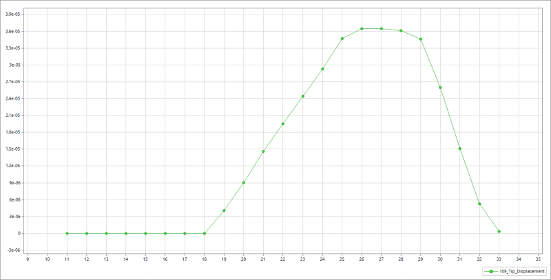
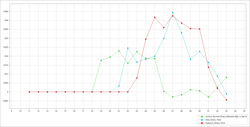
I ran SOL 109 with the above information and I got the output as follows:

Tip Displacement vs Time:
Tip_Displacement_time_zpljt3.png


Axial Stress vs Time (at 3 different locations; near support, middle span element & tip element)
Stress_vs_Time_jptxuc.png


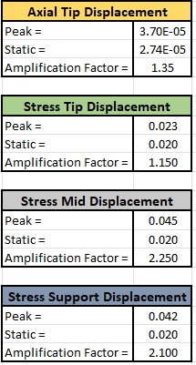
I calculated the magnification factors:
Capture_u8yrco.png


I can certainly see dynamic effects but I would like to hear if the above approach is fine or not!

Thanks again for helping folks!
 
I think your displayed time step is still too coarse to really understand what is going on. How much damping do you have? What is the x axis on the output graphs?

Cheers

Greg Locock


New here? Try reading these, they might help FAQ731-376
 
Hi GregLocock, there is no damping specified. The X axis on the output graphs represent case # (Case 0 will be at 0 sec & Case 33 will be at 7.75E-5 sec)
 
Your force pulse is 26 microseconds long, you've only shown 1 microsecond of the response. I suggest you plot several cycles of the lowest frequency mode, say 200 microseconds.

Cheers

Greg Locock


New here? Try reading these, they might help FAQ731-376
 
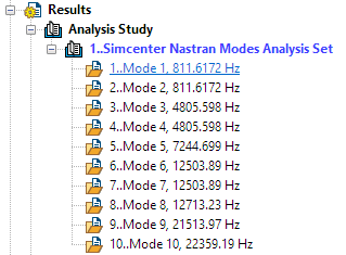
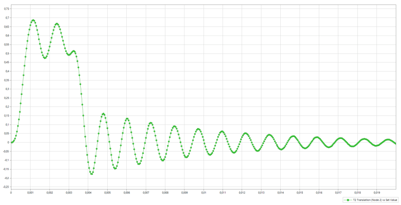
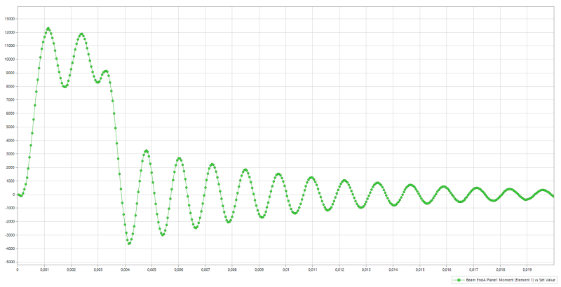
Here I made simple beam model with lateral load that excite first bending mode (811 Hz). You can clearly observe dynamic behavior both on nodes motion and bending moment.
I have included Nastran input files both for Normal Modes and Frequency Response, you can import them into Femap by File->Import->Analysis Model.
I have added 3% damping factor so you can see how oscillations amplitude decrease to zero but this should not affect initial peak values - it is not enough time for damping to dissipate any substantial quantity of energy.
Timestep ~ 1/25 of first mode period.

Burner2k said:
Now for total number of steps, I used what Karachun had mentioned i.e. 1/(12*T) = 1/(12*7.752E-05) = 1075 steps.

I have made error in my description. What i mean is you have oscillation period T=7.752E-05. You calculate timestep dt as (1/20)*T=T/20=7.752E-05/20=3.88E-06 sec.
Now you can estimate whole simulation time as Load Pulse duration + 10 oscillation periods (again rule of thumb, 10 periods should be enough to achieve periodic oscillations so you do not need to calculate further in time). What is load pulse duration? If it is unknown than I would start with 1-3 oscillation periods.

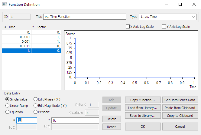
Load_wmbm4v.png

Load

Modes_soyap0.png

Modes

Response1_a3x4kn.png

Response2_p1bakj.png


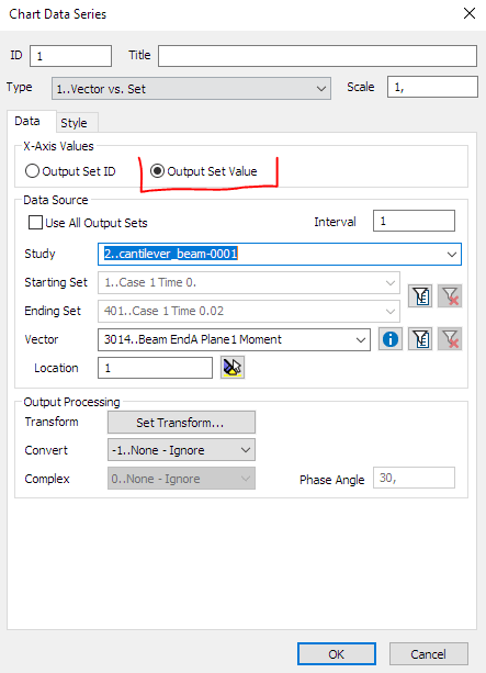
When you plot charts in Femap select "Use output set value" radiobutton so you plot value vs time.
radiobutton_lirfh5.png

 
Karachun,
Thanks for detailed explanation. I will download your sample file and check on weekend.

I have one more question. Perhaps it is a little bit advanced at this stage. In the test example, I know the type of loading and the response from it (Tensile -> stretching/extension) or a simple lateral load will cause bending. From my SOL 103, I can find out which mode freq value I should consider. What if I have a more complicated loading situation where the output (deformation) will be more complex and I run a SOL103. Typically which mode is selected to get an idea about oscillation period?

I hope the above question makes sense!
 
For initial guess you can decompose complex loading into basic directions and think what modes they excite and what not. Than use higher of possible frequencies. Like you have bending and axial load and axial frequency if bigger than use it.
Than to prove that your timestep is small enough you can perform general convergence procedure, like for mesh convergence study: calculate response than divide timestep by two and recalculate response. Select some parameters to compare like peak stress, deformation energy or just plot time history of some result for different timesteps and check if you get some new peaks with timestep reduction. At some point reduction of timestep will not result in any meaningful difference in response so you can assume that you can stop because you don`t get anything new with timestep reduction.
 
Status
Not open for further replies.

Part and Inventory Search

Sponsor