Eng-Tips is the largest engineering community on the Internet

Intelligent Work Forums for Engineering Professionals

Help with Liquid level delimma.

Status
Not open for further replies.

PD2

Industrial
Feb 28, 2024
13
0
0
US
Hello Everyone,

I am a person whom only just got an engineering position and I am having a bit of trouble in a project.
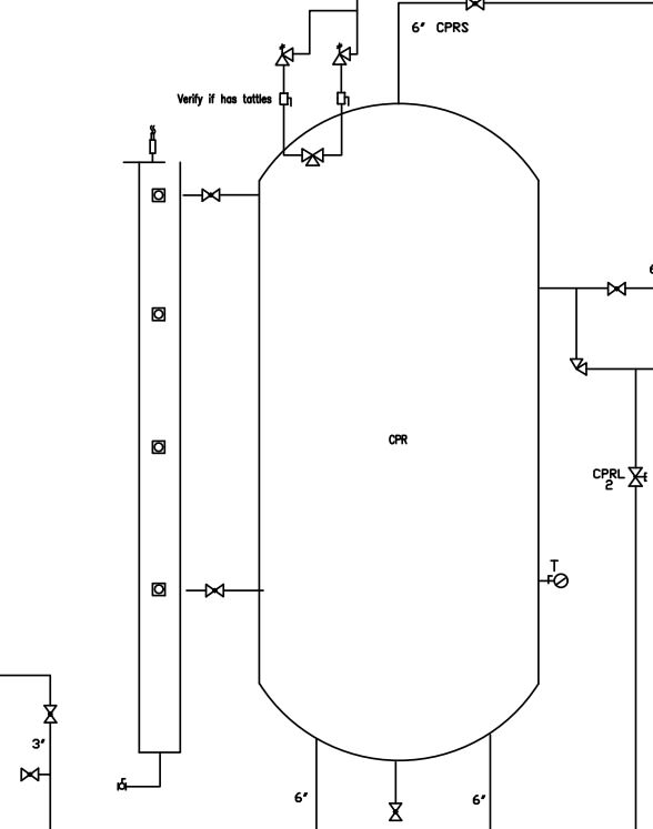
You see, one of the pumps in our refrigeration system is suffering cavitation issues and I am attempting to determine the NPSHa to it. To make a long story short, one of the calculations for this involves the height of the fluid in the Control Pressure Receiver tank located above the pump. This tank is a closed off pressurized vertical cylindrical tank with Ellipsoidal concaved ends.
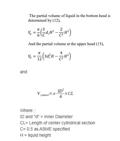
Now, I have already calculated the total volume capacity of the tank using the equations below and attached.

Vbottomend= (Π/6)*(((3/0.5)*ID*(H^2)) -(2/(0.5^2))*H^3))
Vtopend= (π/12)*((3*(ID^2)*H)-((4/(0.5^2))*(H^3))
Vcylinder=(π*((ID^2)/4)*CL)

Where:
ID=Inner diameter (m)
CL=Height of cylindrical section with the continuous cross section (m)
H= Height of liquid itself (m)

For determining the total volume capacity, I substituted the value of "H" with the Tank Head internal depth (IDD).

And we have a program to measure and keep track the percent volume within the tank.


Now, my dilemma is this. I cannot determine any means to calculate the height of the fluid in the tank based on the percent volume. One equation which was shown to me (Height = Total height * (percent volume/total volume) only applied to tanks which were cylindrical with flat ends.

Do any of you know of any solution?


I already tried the method of adding the equations together and solving for H, only for the resulting equation to be a complete mess.
 
 https://files.engineering.com/getfile.aspx?folder=02b76e33-84a7-496a-92f8-3e1db7e06014&file=Screenshot_2024-02-28_084622.jpg
Replies continue below

Recommended for you

A drawing of the tank would help with dimensions, but you seem to have everything you need here.

If you can calculate the volume of the dished end up to some known value of h1 then this gives you a min volume A
Then out of your known volume V, subtract vol A then just solve for h in the cylinder and add it your initial h1.

Or if mm accuracy is not important, just estimate volume in the dished end as though it was a flat end and then think of the vessel as a flat ended vessel.

Remember - More details = better answers
Also: If you get a response it's polite to respond to it.
 
Screenshot_2024-02-28_084622_leylpo.jpg


--Einstein gave the same test to students every year. When asked why he would do something like that, "Because the answers had changed."
 
Pretty sure that C=0.5 means 1:2 eliptical heads

The above formulas assume
Equation 1, H is measured from the bottom of the dish.
Equation 2, H is measured from the bottom cylinder bottom weld seam.
Equation 3, H is measured from the cylinder top weld seam.

The same equations appear here for 2:1 elipitical headed cylinder with a vertical axis

--Einstein gave the same test to students every year. When asked why he would do something like that, "Because the answers had changed."
 
Now, I have another question. The program that my uses to measure the tank levels in percentages uses a parallel liquid column on the tank and it does not span the entire length of the tank. Base on a drawing provided, the top and bottom ends of the column are 3.25 and 81.25 inches respectively from the top of the cylindrical section of the tank.
The calculations above that I had to determine the liquid height level basically had me input a percentage value, multiplying it by the total volume value and using the table to look up the result and its corresponding height level.

All of this was done on the assumption that the program measured the tank level in terms of the percent volume. Now, I am not so sure it works like that simply based on the fact that it doesn't span the entire tank length. I would like to further understand how a liquid column measures the tank level and from that figure out a way to account for this in my calculations.
Attached are pictures of the tank liquid column.

[URL unfurl="true"]https://res.cloudinary.com/engineering-com/image/upload/v1710946391/tips/IMG_6450_y7rjkm.heic[/url]
 
This sort of data should be on the P&ID and should be on the data sheet of the level transmitter.

It looks like the 0 percent / xero reading is some distance above the actual bottom of the tank which I can only assume is the LLL level ( Low Low Level) and if it falls below this the system assumes the tank is empty. If you want to get total volume, then just add this fixed volume to the level on the basis that actual level never falls below this point??

Ditto the 100% reading seems to less than the actual top of the vessel and again I suspect someone has set the 100% to be at or just above HHL.

It makes life easy for the control system as you are then operating by the looks of it in the fixed area of the cylinder where each mm equals the same volume. But find the P&ID and the data sheet and all should be revealed.

Remember - More details = better answers
Also: If you get a response it's polite to respond to it.
 
Thanks for responding. Now I have more questions.
I already have looked at the data sheet and it still gives the percentages, and have the P&ID drawing, but it only shows the liquid column itself and not the
And I already have the total volume of the tank as calculated with the equations above. And what data were you talking about? Do you mean the transmitter set up data?

Screenshot_2024-03-20_114323_hclo2o.jpg
 
Assuming that thing on the left is your level transmitter or guage, then it will only measure levels between the two horiozontal branches at the top and the bottom and probably a bit less than that.

Hence the instrument data sheet should say what is the measured height from 0 to 100%.

So lets say the distance between the taps is 2100mm. The guage will probably only read between 0 to 2000mm allowing 50mm at each end as dead band. Or maybe the data sheet says measuring range is 1850mm, I don't know because you haven't posted it.

unfortunately for you, the total volume of the tank is now meaningless as your zero point or percent measured by the instrument is not the bottom of the vessel, but the bottom of the measuring element in the level transmitter.

Anything thing lower than the bottom tap or higher than the top tap will NOT BE MEASURED BY THE GUAGE.

It's pretty clear therefore that the designers intended the vessel to operate somewhere between the tapping points level.

Operating above the top level may introduce air bubble and air locks and bugger the readings up.


Remember - More details = better answers
Also: If you get a response it's polite to respond to it.
 
Thank for the help. What I ended up doing was calculating the percent volume which wasn't accounted for and adding it to the percentage as measured by the program.
 
Status
Not open for further replies.
Back
Top