Continue to Site

Eng-Tips is the largest engineering community on the Internet

Intelligent Work Forums for Engineering Professionals

  • Congratulations GregLocock on being selected by the Eng-Tips community for having the most helpful posts in the forums last week. Way to Go!

Help with old 11 kV diesel generator

Status
Not open for further replies.

SolarPrestige

Electrical
Mar 4, 2020
38
I have an old diesel generator which has had external modifications and now has issues running; it starts but runs badly. I am trying to narrow down what is installed and as there is very little information available, I am struggling with this. The alternator is 1.5 MVA, operates at 11 kV, is fitted with a rotating brushless exciter and has a black box AVR controller mounted beside it in a panel. It was made by a company named ECC which was based in Wolverhampton England. It was probably manufactured in the 1960s, but with no declaration on any nameplates exactly when. I believe that the black box AVR is a magnetic amplifier unit, but as yet unproven.

This question is related to the brushless exciter. It has a nameplate on the exciter body which describes it as a “DC Generator”. I have seen inside this exciter and it is indeed a brushless unit with six diodes and two wires going into the hollow bored shaft, presumably through to the alternator’s field. The exciter field windings are stationary with rotating armature windings.

Question 1. The nameplate rates the DC generator as 82.5 volts and 3.66 amps (around 302 W). The question I have is that this 82.5 V and 3.66 A presumably is telling me what the exciter’s field is rated to receive? It has been suggested to me that this is what the exciter provides into the main alternator field, but this seems far too low to me. I would expect a 1.5 MVA alternator to require around 15 kW power into its main field (based on 1% rule of thumb). So I think that the nameplate is advising the maximum rating that will be required in the exciter field and this is something that we can measure if we wanted to (we can’t measure the exciters output as there is no access).

Question 2. The nameplate has the text “SEP EXC. OFF 100V”. Any suggestions what this means? I am confused a bit by “SEP EXC” as I take this to mean separately excited and I don’t think that alternator is separately excited. The “OFF 100V” I kind of assume is referring to field flashing requirements but no idea what the O of OFF means. But is this altogether telling me that the field flashing is from a separate source, but then this is really redundant information since field flashing is always a separate source (DC battery from my experience). This generator supplies backup power to a large site so needing a separate source to power the main exciter would be a non-workable solution, unless it was a PMG which this unit does not have.

Any help greatly appreciated.
 
Replies continue below

Recommended for you

Ah!

Diesel generating set runs bad. What does ‘bad’ mean? If it is anything to do with speed or power, in simple terms it is the mechanical side, the engine. Find a diesel engine specialist to fix this.

Electrical side. Electric Construction are long gone. I worked for Hawker Siddeley / Brush who were handed them when Hawker Siddeley bought Aberdare, who owned them and South Wales Switchgear etc. We had no hope for ECC, sorry.

Your exciter is an AC generator but delivers DC Current via the rotating rectifiers. So could be loosely classed as an (ac) generator.
Separate excitation. Looks like the excitation comes from an external source. This set, as you hint, comes before shaft driven permanent magnet generators (PMG), so my ex-Brush generators had their brushless generation powered by terminal mounted step-down transformers. 50 kVA? Open winding, cheap and very unreliable.

These were connected to the generator terminals via fuses. In the case of the Mirrlees Stockport large engines [several megawatts]? (and other engines, Ruston?) the engine set was on a concrete base, with the generator connection into the engine pit. The engine and generator were bolted down separately. Bad engineering but cheap. When it vibrated (as it did) it was the generator manufacturer's fault.

This was done so the engine oil could drip on the electrics. This was all the electrical engineer’s fault

Your size, 1.5 MVA puts in in the Mirrlees Stamford class. Be grateful it has all lasted so long…

At this age, throw any electrical controls away. There is no support available.

There are some competent electrical panel makers who can help you. Try Control and Power Systems
 
Hi Hoxton, yes I know it is old but my client wants to use it, if possible. It was working until the changes were made in the past year, and it should work again at least until the day it finally dies.

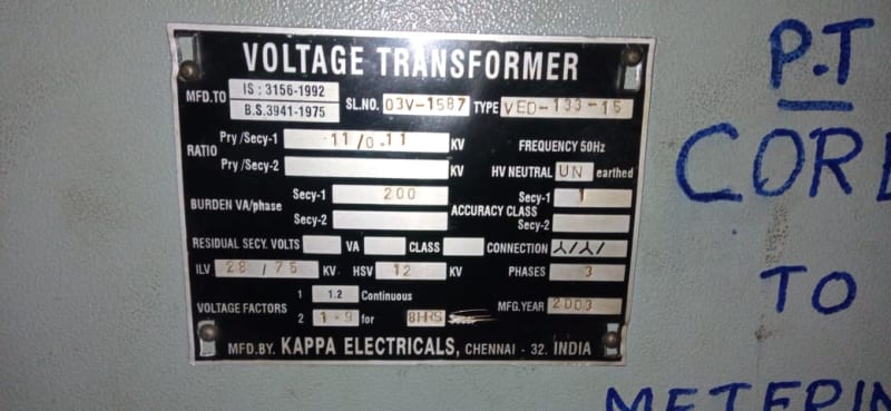
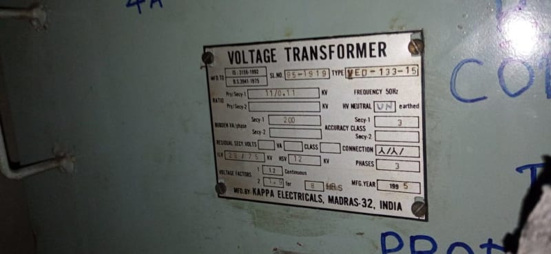
External changes : replaced original 11 kV switchgear with new 11 kV switchgear, which means replaced original VT with new VT. I suspect that the 11 kV VT is used for power supply into the magnetic amplifier and the new VT cannot supply enough VA as it wasn't thought of when the new switchgear was ordered. Hence my question about what the DC Generator/ Exciter nameplate data means.
 
I believe that the black box AVR is a magnetic amplifier unit, but as yet unproven.

Unless the black box is potted or welded shut, it should be a simple matter to remove a cover and have a look within, no? At the same time you can also confirm Schrödinger's cat isn't in there [groan].

I suspect that the 11 kV VT is used for power supply into the magnetic amplifier and the new VT cannot supply enough VA as it wasn't thought of when the new switchgear was ordered.

There's a reason why like-for-like replacements are like-for-like . . . perhaps try a VT of appropriate rating and see what happens, or perhaps do some burden tests to confirm or exclude if what you suspect to be the case actually is.

I hope this helps.

CR

"As iron sharpens iron, so one person sharpens another." [Proverbs 27:17, NIV]
 
Hi crshears. Firstly, this is a problem which someone handed over to me after the original engineer died. The second engineer was unable to devote enough time to it. Now I am the third one looking at this wonderful old school genset

Regarding Magamp, trouble is, how do I know that I am looking at a magnetic amplifier? Such old technology means I am guessing a lot. I see that there are insulated windings sticking out two sides of the AVR box, and a couple of dozen terminals with wires attached. Therefore I assume that it is a magamp but I am far from an expert on what they look like.

Trouble with the appropriate VT question. I would have to find an approx. 500VA 11kV to 440V single phase VT. They are presumably like hens teeth. There is no nameplate on the original VT so I don't know what its VA rating is. I am assuming that the W input to exciter field is the w output of the magamp which is fed from the VA input from said VT. Also, where do I install this new VT - I don't have a spare empty slot in the new switchboard, I will have to get the existing VT extracted and etc.. So this is a special manufacture VT and will cost my client many thousands of dollars and is still only a theory.

This job, in the past year, has created a lot of bad leads and red herrings and what not that I am trawling through. I am trying to put meat onto a working theory of why the genset will now not run correctly.
 
@SolarPrestige

You have pretty much nailed how the system works.

Yes, 82.5 V, 3.66 A is the your brushless exciter's field parameters. The main generator field's voltage and current are much higher and unless it is nameplated, it hard to know these values.

Yes, sep exc 100 V is a field flashing of exciter field when exciter armature loses its residual magnetism. The usual source is battery and it is cut OFF when the exciter armature starts producing voltage on its own with AVR feeding the exciter field.

Muthu
 
Story time:
When I had my contracting and integration biz in Seattle, my ex partner was an older PE with a lot of experience all around the world, so he had a lot of connections. We got a contract offer out of the blue from one of them to pick up an 11kV diesel generator in a Caribbean island of St. Kits, deliver it to a resort in Martinique (French Caribbean island) and refurbish it. He went to look at it, it was total junk. But then he went to the resort to see where it would have to be installed, and discovered that it was a nude resort. So despite having determined the genny was trash, he took on the job. Took him almost 4 months to get the genny running… I kept volunteering to help, he kept saying no, because he didn’t want it to go any faster.


" We are all here on earth to help others; what on earth the others are here for I don't know." -- W. H. Auden
 
SolarPrestige said:
...I know it is old but my client wants to use it, if possible...
Unasked for, but possibly relevant advice- make sure that your client understands the difference between "possible" and "practical"-he/she may have confused the two.
 
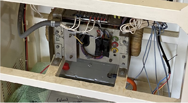
attached image of my AVR which I am assuming is a magnetic amplifier. No data, drawings next to useless, no useful nameplate on this unit. I see winding sticking out the ends and this makes me think, magnetic amplifier. Looks like a toroid style than reactor units, but these were around, I understand.

IMG_0888_c_d_lzykys.jpg


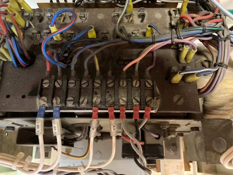
and the terminals

IMG_3421_qnjbhj.jpg
 
Your engine likely has accessory drives. Have you considered attaching a commercially available permanent magnetic generator to the accessory rack to provide power for your voltage regulator? With PM excitation you can sense voltage downstream of your step down transformer.

Have you tried contacting a voltage regulator manufacturer such as Basler to see what options are available? The modern digital regulators are pennies on the dollar performance wise when compared to older regulators.
 
The best resource I have found for old unit replacement or retrofit AVR's is PowerTronics, But most of my work is North America.

I have used this company many times for equipment built and operated in Europe, the Middle East and Africa, They are in the Netherlands.

They have a wide range of products, and very good technical support.

Some of the info found is this area on their website is very helpful in determining just what you need for many older machines,
Nominal 82V and 4A was common on several Newage Stamford generator ends for many years, older AVR's on those units were replaced with the current AS440 regulator. Avk (before being bought by Stamford/Cummins) also used 82VDC nominal voltage regulation, but usually at 6-8 amps, at least on the units have dealt with.

If you could post some additional pictures of the AVR connections and the drawings you have it may get you some more help. You don't have to appear to have much experience in generators and their AVR's, so what's on the available drawings may not make sense to you, but several folks on this forum have quite a bit of generator experience and may find something in that documentation that provides some insight.

Your AVR looks similar some older Brush AVR's for SE (Static Excited) generators that had an integrated series boost module, but without nameplate data or more info is hard to tell if that's the case.

Hope that helps, MikeL.
 
Hi TugBoatEng. Accessory drives, not sure; are these going to be accessible on the side of engine? Not sure that there is anything at the far end of the engine, don't have a good photo of that.

A replacement AVR may be an option, but only with a PMG installed as well, which is what you are talking about. Not at that stage yet, but useful to know that is an option. My question regarding the power input to the exciter is relevant to that as well.

Thanks Edison123, good to read that this is the correct way to read the exciter nameplate.

My views are going to challenge some other people who have ideas about what needs to be done to get the unit running again. My plan is to test run the unit with 400 Vac phase-phase off a local 400V DB, and connect this to where the VT normally goes, so replacing 440V VT input with 400V. This should at least satisfy the VA required in the AVR which I think is around 500VA or even more. I expect that the AVR will drive the alternator voltage as high as it can from this test, so have to keep a careful eye on generator voltage level.
 
Hi Catserveng. The problem is not being unfamiliar with generator and diesel gensets, the problem is I have not worked with anything this old. First time seeing a magnetic amplifier, never saw one before this job, assuming that is what it is.

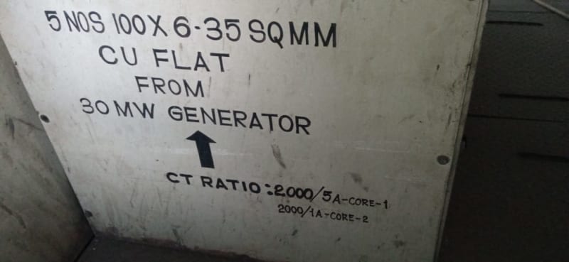
I have people telling me that there's an amplidyne powering this unit - there isn't. People reading a CT nameplate and buying VT interfaces based on that; no, that's the data for the CT. That caused a lot of confusion.

There is nothing in the electrical drawings that is helpful to me. Nobody knows what happens inside the black box. Interesting idea that it might be static, but then it needs power externally, and as this is a black start unit, that would need something reliable. There are only small batteries around this unit, so I don't know, maybe the static could be DC powered, but this is not shown on the drawings.

Good anyway to hear that 82 V was a common voltage used for exciter fields.

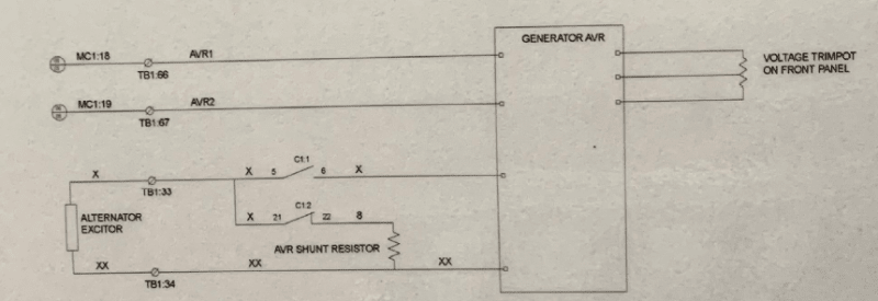
Cap_AVR_faxms8.png


the data next on this VT is incorrect. We have tested it as 11000:440 Vac (not 230 Vac as noted)

Cap_Gen_VT_y7t6gd.png


these drawings were created about 30 to 40 years after the unit was installed. I can't believe a lot of it as I see mistakes in many places on the drawings.
 
@OP

Refurbishment of mothballed old generators is easily doable at a fraction of the cost and lead time of a new one. I do it all the time. AVR's not requiring a PMG have been on the scene for a long time now. I am presently doing the refurbishment of a 27 year old Skoda 30 MW, 3000 RPM TG brushless exciter rotor, which has a functioning PMG but is not used. I will try to get the details of the AVR this client is using. Getting the VT and CT with required burden for the AVR costs next to nothing.

Muthu
 
The problem is not being unfamiliar with generator and diesel gensets, the problem is I have not worked with anything this old.

Perfect. Use your current knowledge to update the unfamiliar systems. You have identified a critical system that requires manufacturer support and spares that don't exist. The AVR can be replaced with with a commercially available option, you may need some custom transformer to power it.

From my previous post, engines often have power take off drivers opposite the flywheel end of the engine. These could be useful to drive a permanent magnetic generator. Consider this option only if there isn't room on the generator shaft to install a PMG.
 
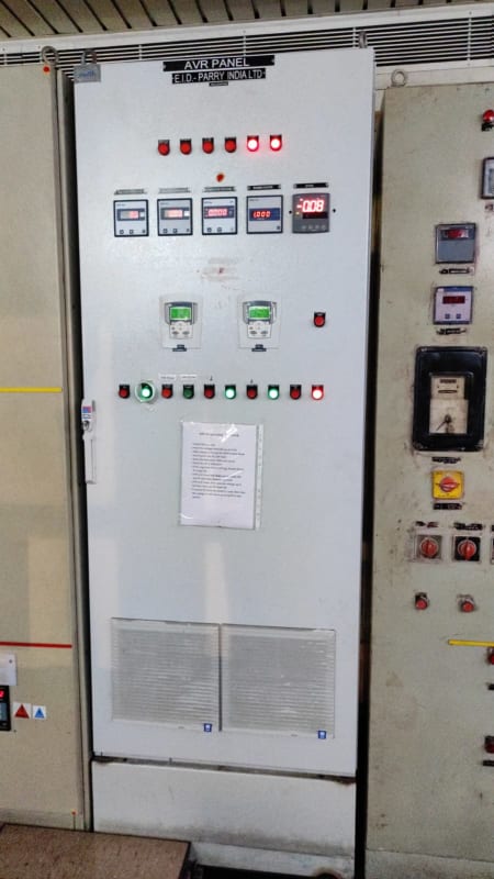
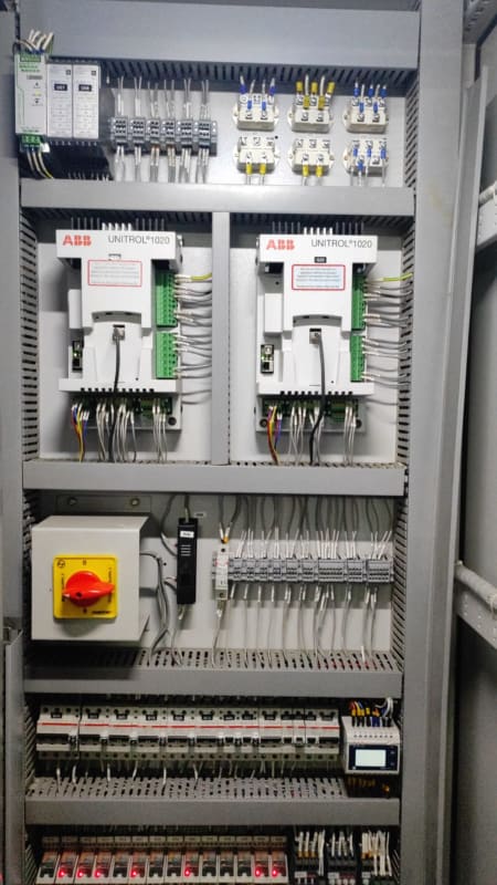
Nice photos and I see Unitrol modules, small ones. I have seen these around on other plant. The biggest one I worked with was feeding a 500MVA generator so that was a set of six panels fed by a 3.8 MVA excitation transformer. That system was quite complex while my old school 1.5 MVA unit is simple, but so far from understood that it seems much more difficult.

thanks for the info.
 
A lot of old exciter generators were converted to AC brushless exciters.
Each winding in a generator armature generates a sine wave.
The commutator commutes or reverses the connections to each winding twice each cycle.
If you tap off of three commutator bars at 120 degrees apart, you will get three phase voltage.
The poor mans solution would be to then cover the commutator bars with Glyptal or some other insulating paint.
Most conversions involved removing the commutator and rewinding the armature.
Same winding, just no connection to a commutator.
I worked on a lot of those converted sets.
AVRs were around a lot longer than PMG exciters.
And, most PMG exciters fed power to the AVR which controlled a conventional brushless exciter.
In the event of a PMG failure, the set could be run with a non PMG AVR until replacements could be obtained.

--------------------
Ohm's law
Not just a good idea;
It's the LAW!
 
Status
Not open for further replies.

Part and Inventory Search

Sponsor