Continue to Site

Eng-Tips is the largest engineering community on the Internet

Intelligent Work Forums for Engineering Professionals

  • Congratulations cowski on being selected by the Eng-Tips community for having the most helpful posts in the forums last week. Way to Go!

Help with positional measurement of microprocessor leads

Status
Not open for further replies.

jmccann

Electrical
Sep 18, 2015
7
I'm a lowly measurement technician. They sent me to GD&T training, but it was mostly about theory and applying the principles when drafting up a design drawing. None that helps much when trying to actually measure things using GD&T. There's no one around for me to ask for help, so I'm coming to this forum.

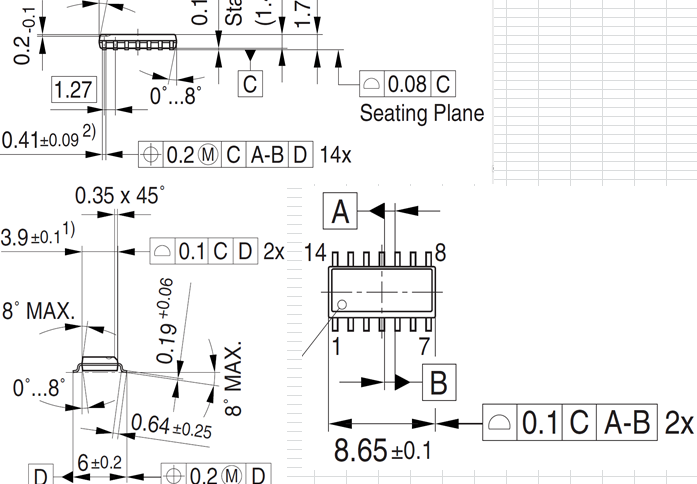
This is a microprocessor drawing with lots of GD&T on it. The questions I have are about the two positional ones. My problem is, the only way I know to do position is an x y coordinate deal with maybe the Pythagorean equation. In this image, I don't have but the one basic dimension in the whole drawing. I'm at a loss as to how they expect this positional measurement to get done. Am I just measuring the distance between a pin middle and the adjacent one, and then taking the absolute difference from the basic dimension? If that were the case, I could only measure 13 instances and not 14 like it asks.

I have a suspicion that GD&T was just plain used incorrectly on this drawing.

Thanks to those that help


Capture_lh02d9.png
 
Replies continue below

Recommended for you

Notice that those two position callouts do not have a diameter symbol before their numbers. Thus, they are only asking for position in that one direction (left-right, as seen in the picture you give). You are checking to see if the center plane of the designated feature (pin/lead/pad/whatever) is more than 0.1 to the left or the right of its perfect location. So no need to worry about the Pythagorean theorem or any of that.
(Actually, they could be more than 0.1 to either side since they each show the "M" symbol -- you should remember the stuff about MMC and bonus tolerance from your training...)

John-Paul Belanger
Certified Sr. GD&T Professional
Geometric Learning Systems
 
The tolerance zone for true position, without a diameter symbol, is not round. It's default tolerance zone is actually two parallel planes, the specified tolerance apart. So, like the gentleman above me said, they only want you to check the position of each pin in one direction.

I have one question... Why does your company have you measuring chip components like this? Do you guys manufacture these IC's? Or are you buying them from someone else and using them in your designs? Just curious.

Please, please, please, use the correct terms!They're Datum Features NOT DATUMS!!! AAAAAHAHAHAHHAHAHAHHAAAAA" -- Don Day
 
Thanks for the help. One thing though, the positional call out with lots of datum features is solved, but the second positional call out still doesn't have a basic dimension to use with it. Am I really supposed to do parallelism measurement of one exterior pin tip to the opposite exterior pin tip? If so, why didn't the drawing just say so?

The part is supplied, not manufactured by the company I work for.
 
At teh bottom of the image there is a positional callout to datum D while at the same time the feature IS datum feature D. That's not right.

John Acosta, GDTP Senior Level
Manufacturing Engineering Tech
SSG, U.S. Army
Taji, Iraq OIF II
 
It's a typical example of EEs applying Y14.5 to electrical parts. It's not intended for actual inspection.

For example, C|A-B by iteself immobilizes the part; there's no need to refer to D in the 14X position FCF.

There's an EE standards group, JEDEC, that has examples for all the packages and the ones I saw are inconclusive like this one.
 
Bumping. Still one question unanswered. On the Positional feature frame with only Datum Feature "D" called out what am I actually measuring? There is no basic dimension to use there.
 
That's what I referred to in my first response. This callout is bogus.

John Acosta, GDTP Senior Level
Manufacturing Engineering Tech
SSG, U.S. Army
Taji, Iraq OIF II
 
Status
Not open for further replies.

Part and Inventory Search

Sponsor