Continue to Site

Eng-Tips is the largest engineering community on the Internet

Intelligent Work Forums for Engineering Professionals

  • Congratulations GregLocock on being selected by the Eng-Tips community for having the most helpful posts in the forums last week. Way to Go!

Help with Positional Toleranceing for Symmetry 3

Status
Not open for further replies.

AXNRXN

Mechanical
Jan 20, 2009
34
Hey All,

I have a formed sheet metal part similar to that shown. Dataum A is the flat back surface, Datum B is defined by a hole perpendicular to A. Datum C is defined as the center plane of a slot. I want the ears of the sheet metal part to by symmetric to a center plane running through the center or the part. I know that you don't use Symmetry, so I want to call it out with Position tolerance. What are you thoughts of creating a Datum D which is the center plane bewteen the hole and the slot? This is off of a basic dimension which is kinda weird to me. Or, any other way to set this up so that the ears are located by a Position tolerance relative to a center plane?
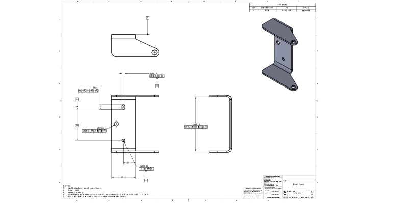
temp_part_1_zzs8m0.jpg

Thanks for any help!
 
Replies continue below

Recommended for you

chez311,

ASME Y14.5.1M-1994 para. 2.3.1(b) said:
F conforms to its limits of size if:
[ul]
[li]HlHm[/li]
[li]FHm - Hl[/li]
[li]F surrounds (encloses) the boundary of Hl (if F is an external feature) or the boundary of Hm (if F is an internal feature).[/li]
[/ul]

The third bullet point is an attempt to close a loophole. The second just says that the surface must fall within the tolerance zone. The first is what allows this definition to control unopposed surface elements. The envelope principle is not required for this, but it can influence the result.

I think the first bullet point also complicates the determination of actual values, but perhaps that is an issue best set aside for the moment.


Could you clarify a little by what you mean by this? Are you considering cases where there is instability or multiple solutions (ie: rocking) ? Do you believe the interpretation per Y14.5.1-1994 is more robust or "better" or just different?

There will almost surely be only one correct solution for the UAME, so I am considering cases where multiple envelopes with significantly different locations appear to be indistinguishably good candidates. One example would be a nominally cylindrical hole that is actually produced as a slot with two nearly parallel sides and two rounded ends.

I believe the Y14.5.1M-1994 definition is more robust in the sense that a small change to the actual surface will not produce a large change in the actual values of feature size. This sort of stability is a desirable characteristic, but it's certainly not the only one. I wouldn't want to declare either definition a clear winner at the moment.


pylfrm
 
pylfrm,

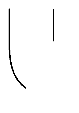
My apologies - I took a few days off for a much needed vacation. I much appreciate your pointing me in the direction of the above statements in Y14.5.1 - however I'm not sure I fully grasp how this covers all cases of opposed points without requiring the envelope principle. Take the case we have been discussing (a feature bounded by one short and one long side). If the portion of the long side which is unopposed begins to curve (like in the simplistic figure below), what prevents unlimited variation of this curved portion? It seems to me that without the envelope principle, there can always be found two solids Gl and Gm (for an external figure Hl = Gl and Hm = Gm) which satisfies those bullet points. Perhaps I'm missing something..

curved_unopposed_wuul8m.png


There will almost surely be only one correct solution for the UAME, so I am considering cases where multiple envelopes with significantly different locations appear to be indistinguishably good candidates.

To my untrained eye these seem to be conflicting statements. Do you mean "one correct solution" per the actual measured value (ie: the value with whatever precision/number of decimal places the measurement device reports) but when measurement uncertainty is included can result in "indistinguishably good candidates"?
 
chez311,

I really just meant that the third bullet point is still relevant in cases where the envelope principle doesn't apply. Something like this might be a good example, although it would be more dramatic with 150° of the cylindrical surface removed instead of 60°.

The envelope principle certainly makes a huge difference for features like OP's 50+/-0.25 width. Without it, the surface with unopposed elements can indeed behave as you show. I don't think you're missing anything.

One thing to keep in mind with these definitions is the need for the spines to be "reasonable". Unfortunately ASME Y14.5.1M-1994 doesn't appear to mention this at all. I think the draft for the next revision illustrates various ways to achieve unintended results with "unreasonable" spines, but doesn't provide a mathematical fix for the issue.


Do you mean "one correct solution" per the actual measured value (ie: the value with whatever precision/number of decimal places the measurement device reports) but when measurement uncertainty is included can result in "indistinguishably good candidates"?

I mean that the probability of a feature truly having multiple distinct UAMEs is zero. The measured sizes of candidate envelopes might be identical, or they might differ by an amount that is small compared to the size measurement uncertainty. Either way, you can't confidently pick a winner.


pylfrm
 
pylfrm,

I see now, the D-shaped shaft is a good example of what you are talking about. The envelope principle could be removed in that case and the concept in Y14.5.1 would work relatively well to control size of portions with unopposed points even with significant form variation. As the percentage of the feature is unopposed increases (approaches 180deg of the cylindrical surface removed) I reason this becomes less true though.

Considering this - if we do not apply the envelope principle to a feature per Y14.5-2018 the control of size of unopposed portions would still be based on the UAME. This could be problematic as the allowable form variation could show up as size variation and reject a part which could be perfectly acceptable functionally and the definition per Y14.5.1 would allow, right?

The envelope principle certainly makes a huge difference for features like OP's 50+/-0.25 width. Without it, the surface with unopposed elements can indeed behave as you show. I don't think you're missing anything.

Okay good, I thought perhaps there was another interpretation of the Y14.5.1 concept that I was missing. Thank you for spelling that out for me.

Good point about the spines though, when you say "reasonable" I assume you mean whats mentioned in the draft about establishing a "tangent-continuous" local size spine as well as the improper application of spines as shown in Appendix F ? It certainly would be helpful as you say to derive mathematically what is acceptable or not.
 
As the percentage of the feature is unopposed increases (approaches 180deg of the cylindrical surface removed) I reason this becomes less true though.

Why do you say that?


Considering this - if we do not apply the envelope principle to a feature per Y14.5-2018 the control of size of unopposed portions would still be based on the UAME. This could be problematic as the allowable form variation could show up as size variation and reject a part which could be perfectly acceptable functionally and the definition per Y14.5.1 would allow, right?

I don't see why the rule about unopposed points would be considered part of the envelope principle, but it's under the heading "Variations of Form (Rule #1: Envelope Principle)". Perhaps that means it doesn't apply in a case like the D-profile shaft where a straightness tolerance overrides the envelope principle. Thoughts?

(Again, this is based on the draft. Hopefully you can verify that there are no relevant differences.)


Good point about the spines though, when you say "reasonable" I assume you mean whats mentioned in the draft about establishing a "tangent-continuous" local size spine as well as the improper application of spines as shown in Appendix F ?

When I say "reasonable" I am referring to the subject of Appendix F. Mainly this means common sense should be used.

Tangent continuity is less relevant. Perhaps it could be argued that all reasonable spines are tangent-continuous, but the converse is certainly not true.


pylfrm
 
Why do you say that?

After further considering it, I don't think I stand by my initial statement.

I don't see why the rule about unopposed points would be considered part of the envelope principle, but it's under the heading "Variations of Form (Rule #1: Envelope Principle)". Perhaps that means it doesn't apply in a case like the D-profile shaft where a straightness tolerance overrides the envelope principle.

Thats a fair assessment. The 5.8.1 is the section for Rule #1: The Envelope Principle (Variations of Form) as you say - I hadn't initially considered it to be so, but perhaps it indeed only applies when the envelope principle applies. As it says "The form of an individual regular feature of size is controlled by its limits of size to the extent prescribed in (a) through (e) below" and 5.8.1(e) is the unopposed points concept we have been discussing. Exceptions to Rule #1 per 5.8.2 are cases when "The control of geometric form prescribed by limits of size does not apply". I don't see why as you note the rule about unopposed points must be considered part of the envelope principle, however the potential issue I stated previously might be why it is.
 
Status
Not open for further replies.

Part and Inventory Search

Sponsor