Continue to Site

Eng-Tips is the largest engineering community on the Internet

Intelligent Work Forums for Engineering Professionals

  • Congratulations KootK on being selected by the Eng-Tips community for having the most helpful posts in the forums last week. Way to Go!

Help with sizing of lug attachment flange

Status
Not open for further replies.

hootrpootr

Aerospace
Feb 28, 2020
27
Hello,

Apologies for the crude drawing attached, but here goes. Given Fx, Fy, and Fz loads applied at the lug hole, I've distributed the loading into each of the 6 fasteners to size them. I've also sized the lug itself using the airforce lug sizing method.

But now I'm trying to size the portion of the lug fitting that I've labeled as "lug flange" and am kind of hitting a wall. Are there any methods to size that part? I know I could throw this into FEM for sizing, but I'm thinking to size it by hand, I could separately determine the bending stresses created in the x, y, and z directions and then superimpose them? And then also check the pull through and shear out due to the fasteners into the flange?

Any thoughts are greatly appreciated. Thanks
 
 https://files.engineering.com/getfile.aspx?folder=a378f1d5-010e-4f81-9286-9a117cd45964&file=unnamed.jpg
Replies continue below

Recommended for you

Below is the general procedure:

1) Get average bolt force in x and y direction, Fv[sub](x,y)[/sub] = F[sub](x,y)[/sub]/# bolts.
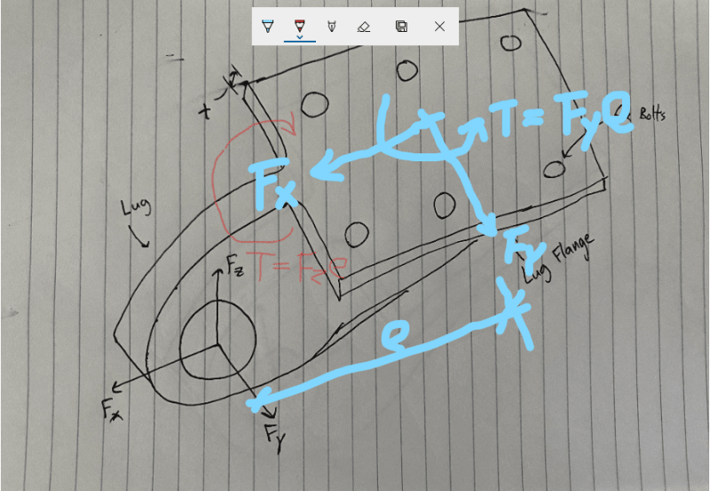
2) The force Fy will cause a torque on the center of the bolt group, distribute the torque to each bolt and get Ft.
3) Combine Fv[sub](x,y)[/sub] and Ft, then use plate bearing limit to get thickness.
4) Check shear on the net area in direction of x and y.
 
Thank you for the response r13! But for step 2, wouldn’t Fz be the force component that creates a torque at the center of the bolt group, not Fy?
 
No. Fz produce a torsion that causing tension on the bolt, and compression on the plate. Fy produce a torque torsion in the plane of the plate, that distribute shear force to the bolts. In plane shear is the main concern for sizing plate thickness. I assume you have sized the bolt already, so Fz (out of plane force) is not in the play.

image_ktha8k.png
 

You did not define whether the bolts preloaded or not...

Assume no preload , ( the bolts snug tight or finger tight,)

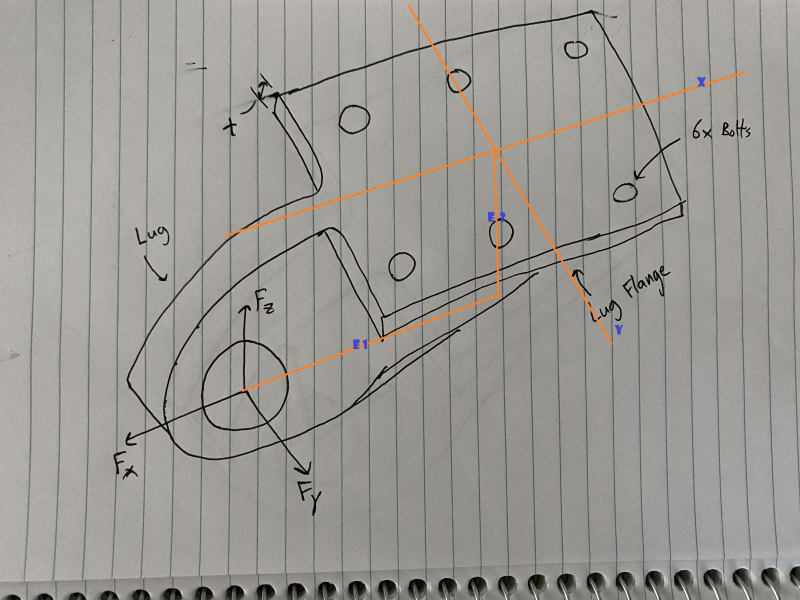
You are expected to transfer the loads to the CG of bolt group. In this case , there are two eccentricities . Forces Fx and Fz will create moment about Y axis, while Fy will create Torsion about Z axis and moment about X axis.

Now the moments;

Torsion ( about Z axis ) Tz= Fy* e1

Moment about Y axis My= Fz* e1 + Fx * e2

Moment abot X axis Mx = Fy * e2

Then you are expected to find the shear stresses ( due to shears VX and VY ) and ( due to torsion).

Notice that, some of the bolts will experience tension due to Mx and My. You can find the procedure from mech. eng hanbooks . (e.g. Walter D. Pilkey - Formulas for Stress, Strain,)..
I tried to show the eccentricities on your sketch ..

unnamed_p7bqhk.jpg
 
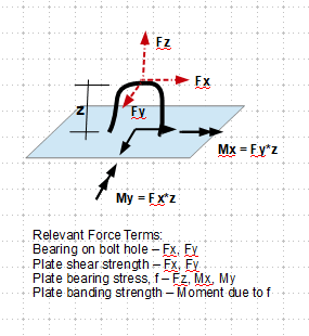
I must have fallen sleep. The log is T, the log eye is aligned with the center of the plate and the bolt group, so there is no in-plane torsion/twisting, but out plane bending. So, sizing the plate by bolt bearing, and critical shear due to Fx and Fy is suffice.
 
Recoup from previous mistake/omission:

image_dfdick.png
 
Status
Not open for further replies.

Part and Inventory Search

Sponsor