hootrpootr
Aerospace
Hello,
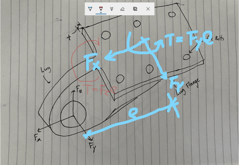
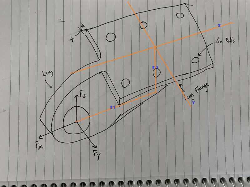
Apologies for the crude drawing attached, but here goes. Given Fx, Fy, and Fz loads applied at the lug hole, I've distributed the loading into each of the 6 fasteners to size them. I've also sized the lug itself using the airforce lug sizing method.
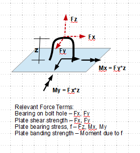
But now I'm trying to size the portion of the lug fitting that I've labeled as "lug flange" and am kind of hitting a wall. Are there any methods to size that part? I know I could throw this into FEM for sizing, but I'm thinking to size it by hand, I could separately determine the bending stresses created in the x, y, and z directions and then superimpose them? And then also check the pull through and shear out due to the fasteners into the flange?
Any thoughts are greatly appreciated. Thanks


