Eng-Tips is the largest engineering community on the Internet

Intelligent Work Forums for Engineering Professionals

Heritage: Early 20th century power generation 1

Status
Not open for further replies.

Vegemite

Electrical
Jul 28, 2002
28
0
0
AU
Dear Heritage Buffs, I am reading a report from 1912 in which the author is comparing rotary converters with motor-generator sets for the conversion of 440 V AC to 600 V DC for tramways use. Can you please explain the difference? In another report the DC power stations of that time are said to have an electrical machine described as a 'balancer'. Could you please help with this as I can find no description of this device?
 
Replies continue below

Recommended for you

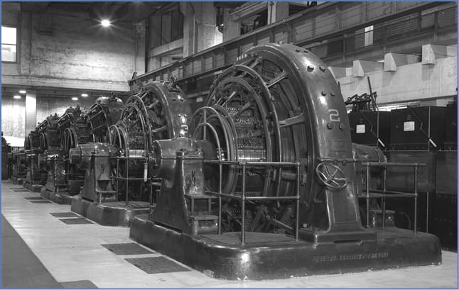
An MG set or motor-generator set is either an induction motor or a synchronous motor driving a DC generator.
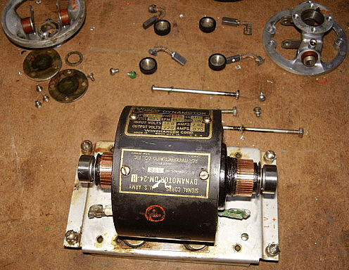
A Rotary Converter is a device that shares a rotor with both the AC circuit and the DC circuit.
The AC section may be wired for single phase, 90 degree two phase or three phase.
The single phase unit needs a starting circuit to work with a single phase input.
90 degree two phase has gone the way of the dodo.
The AC input may be three phase.
While these are most commonly used to produce DC from an AC supply, they are reversible and will produce AC if driven by a DC input.
Only very small units may be started DOL on DC.
Larger units need DC motor starters to limit the starting current if used for DC to AC conversion.

Back in the 50s diesel driven alternators typically had a shaft mounted DC exciter. The DC was drawn off through brushes and a commutator and fed back into the rotating assembly by brushes sliprings to energize a rotating field.
Then brushless exciters were developed.
The brushless exciter developed three phase AC which was conducted to a rotating diode plate and rectified to supply the DC field windings.
This eliminated both the commutator, the slip rings, all the brushes and a lot of maintenance.
Then someone realized that while the commutator extracted DC, each individual coil generated AC.
By tapping (connecting to) three equally spaced commutator segments, three phase AC could be extracted.
A rotating diode plate was fabricated and many brushed DC exciters were converted to brushless exciters.
The shops doing the conversions typically removed the commutators and brush gear.
What does this have to do with rotary converters?
It illustrates the use of the same rotor winding for either AC or DC.
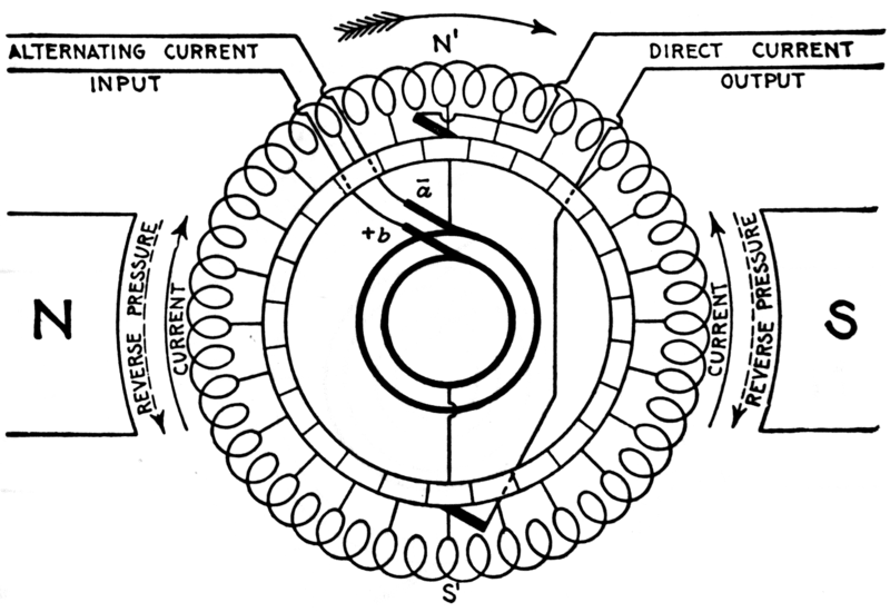
This is the principle of a rotary converter.


Here is a single phase rotary convertor.
image_x9d26g.png

Here is a three phase rotary convertor.
Which to use?
Rotary Converter:
Smaller applications with similar AC and DC voltages. The rotary convertor may be used.

Motor generators:
Larger installations.
Different AC and DC voltages.
One motor may drive more than one DC generator.
Spares, often but not always, the DC generator may be identical and interchangeable with the motor which it is driving.
Easy starting, speed control, speed regulation and reversing of DC motors.
by field strength control of the individual generators.

Bill
--------------------
Ohm's law
Not just a good idea;
It's the LAW!
 
I have seen a balancer explained in a Audels Electric Library.
Its purpose is to create a neutral - similar to a zig zag grounding transformer, but for A DC distribution system. The configuration was a motor, with a commutator, and a single slip ring. The windings are arranged so the slipring is ZERO volts, and the brushes are +125 and -125, or what ever the system is supposed to provide.
 
I can't find anything on the 'net about balancer sets.
That gives some idea of the age of that technology.
If I come across something in a very old book, I'll post again.
I don't trust my memory without a refresh.
I lost my Audel's Electric Library about 50 years ago.

Bill
--------------------
Ohm's law
Not just a good idea;
It's the LAW!
 
Yes rotary converters were used for converting 25Hz to 60Hz also.

I have also seen MG sets used for short outage ride through.

However, the only balancer I have heard of is a harmonic balancer on a generator.
As nobody wants transit torques on their generator shaft.

 
Balancer sets were used on center tapped systems such as 110/220 Volt systems.
I can't see how a rotary converter may be used to convert 25 Hz to 60 Hz.
An MG set with a synchronous speed of 300 RPM would work.
If the purpose is not to match grids but to use 60 Hz equipment on a 25 Hz system a higher speed may be close enough and easier to source.
Another option may be a belt drive or a gear reducer.


Bill
--------------------
Ohm's law
Not just a good idea;
It's the LAW!
 
Until the 80's the power supplied in the Loop of Chicago was DC. So major building all had their own MG sets.
I have even seen small briefcase sized ones for spot use.

= = = = = = = = = = = = = = = = = = = =
P.E. Metallurgy, consulting work welcomed
 
DC service was supplied to downtown Vancouver Canada buildings mainly for running elevators.
As the electric bus routes were being eliminated solid state rectifiers were installed to power the elevators.

The "T" transformer was also used to transform three phase to three phase.
I saw quite a few "T" transformers in industrial plants in the 70s.
Typically 25 KVA to 37.5 KVA, 480 Volts to 120/208 volts to power a 100 Amp lighting panel.

Bill
--------------------
Ohm's law
Not just a good idea;
It's the LAW!
 
Additional information is in Volume 3, section 13, page 44 of the ICS Reference Library... but I don't see it listed at the URL given in my earlier reply.
It appears I have the volume that is missing at the site. Hmmmm? Interesting.

John

Edit: My mistake, Volume 3 is at the site.
 
Rotary converters for 60 Hz to 25 Hz are probably a bit more complicated to build than motor generators. In either case you have big machines with lots of poles to avoid the complication of gearing.
Number of poles required
(60/25)*2=4.8
4.8*10=48

Shaft Speed
(60/48)*2 = 3 r/s = 150 rpm

Amtrack still has some very large MG sets in service. These were all installed with the original electrification prior to 1930.
The pole ratio in 50 Hz land is just a factor of 2 so the conversion could be performed with a 4 pole MG or converter. That makes the now removed 50 Hz systems in the US and Canada have a rather strong historical reason to have existed.
 
My Dear History Buffs,
Many thanks for the replies. All of them are engaging and educational.
Dear Waross, Would you kindly confirm that the rotary converter's winding, or windings if polyphase, are common to both the AC and DC circuits?
Dear dArsonval, I am sure I will find my 'DC Balancer' in one or more of the ICS Reference Library documents. It is a treasure trove.
Let me explain the recommendations made in 1912 by one of many consultants in connection with upgrading a 440 V DC power system with three separate power stations whose busbars were connected to form a solid grid devoid of any organised feeder structure.
Firstly, he recommended a centralised power station utilising HV (no more than 12,000 V) AC transmission to a number of step down substations.
At each substation he recommended 50 Hz (at what I assume to be 440 V) for the lighting supply and DC for powering motors, all of which would have been DC at the time of his report.
He preferred motor generator sets to rotary convertors as he believed:

[ul]
[li]they were more reliable and,
[/li]
[li] if of the synchronous type could be adjusted to run at unity power factor.[/li]
[/ul]

As peak load in those days was on Friday evenings when the late night shopping in the city center had all of the shops and entertainment venues fully lit, he suggested a battery in each substation that could:
[ul]help with peak lopping on these evenings
[li]enable the entire HV system to be shutdown for cleaning (from, say, midnight Saturday until 4 PM on Sunday) with the batteries supporting both the AC and the DC loads
For this reason he recommended that the motor generator sets be reversible (and this probably supported his preference for the synchronous AC machine as opposed to an induction motor) [/li]
[/ul]
For information, his scheme was not adopted. Mr Charles Merz was later engaged and he recommended completely scrapping the DC motors and converting the entire distribution system to 400 Volts and 50 Hz.
Strangely, the as-installed system ended up as follows:
[ul]central power station generating at 40 Hz
6,000 V AC transmission to the city area and immediate surrounds
20,000 V transmission to remote locations
440 V AC distribution for all power and lighting (other than tramways supplies)
for the tramways; 6,000 V AC/600 V DC British Westinghouse rotary converters (I do not know if they were induction or synchronous but I was reliably informed that if you stood near one when one of the DC circuit breakers tripped you could get injured by a large arc that developed between the units and the surrounding metal guard rails.)[/ul]

In the 1950s the system was converted to 50 Hz and around the 1980s or 90s the voltage was reduced from 440 V to 415 V (but we still regularly get 250 V on our 240 V single phase supply.)
 
If the device is a rotary converter, the windings on both ends of the machine are in common. One end will have sliprings, the other end will have either sliprings or a commutator.
If the two ends of the device are electrically independent, then the device is a motor generator.

There is a variation of the motor generator called a synchronous phase converter, which was a single-phase synchronous motor and a three-phase synchronous generator with common stator and rotor. The synchronous phase converter was used mostly in European electric locomotives to connect the 16 2/3 Hz single phase catinary power to whatever the traction motors needed.
The rotary converter winding diagram simplified. (the same one waross provided)
Screenshot_from_2021-02-17_17-19-30_dbensh.png


history06-2313802_fmt_c62ltf.jpg


Surprisingly there is still 1 operating hydroplant producing power at 40 Hz in the US
 
Has anyone mentioned the dynamotor?
This was a DC machine with two windings in the same slots and a commutator at each end.
One winding may be for 6 Volts or 12 volts and the second winding would be for several hundreds of Volts and be connected to a second commutator on the opposite end of the armature.
The low voltage winding was used to drive the device as a motor.
They were used to produce plate voltage for mobile radio transmitters.


Bill
--------------------
Ohm's law
Not just a good idea;
It's the LAW!
 
I wish I had pics of them; prior to said frequency change-over, two units at the Sir Adam Beck I Generating Station north of Niagara Falls, Ontario, Canada, were converted into 25 Hz/60 Hz frequency changers, with all water passages retired and, if I understand it correctly, their vertical shaft Hydraulic turbines stripped out and replaced with 60 Hz machines, with the 25 Hz alternators subsequently re-installed above them.

The units essentially ran 24/7/365, and were only occasionally shut down for maintenance. Re-starting them was accomplished by locking together the fields of one side of the frequency changer with another appropriate-frequency hydraulic generating unit at rest, then starting the hydraulic generator and frequency changer as one unit. It is my understanding that since neither unit employed stator shifting, both the 25 Hz and 60 Hz synchroscopes were observed to ensure both were at or very near zero before the synch breakers were closed. By this means the two units would share load very nicely.

The underlying purpose of these FCs was to stabilize the eventually-much-smaller 25 Hz system by "anchoring" it to the 60 Hz system; 25 Hz hydraulic genarators were loaded / unloaded / added to / removed from the system so as to always operate the FCs within their continuous ratings. Apparently there was no N-1 criterion applied to the loadings of the FCs as in the event of loss of one FC the governors of the connected generators could be rapidly maneuvered in such a way as to promptly relieve any overload on the surviving FC unit.

CR

"As iron sharpens iron, so one person sharpens another." [Proverbs 27:17, NIV]
 
Years ago I read an article in an engineering magazine about a 60 Hz to 25 Hz conversion.
A plant had a large 25 Hz induction furnace.
The utility was phasing out 25 Hz service.
Management looked at the cost of converting the furnace to 60 Hz and looked at the cost of a new 60 Hz furnace.
Then they asked the engineers if there was any way that they could devise to keep the furnace in service at minimal cosy.
They had a large inventory of spare motors, 25 Hz and 60 Hz.
Many of the motors were synchronous motors.
The solution; A 60 Hz to 25 Hz MG set built with on hand, spare motors.
The second challenge was capacity; They did not have any individual generators of sufficient capacity to run the furnace.
The solution was to run MG sets in Parallel.
The third challenge; Synchronization.
With synchronous machines, the phase angles were locked no matter what the relationship.
The solution; They fabricated a coupling with an adjustable angle.
The sets would be run and the phase relationship observed on a scope.
The sets would then be stopped and an adjustment made on the coupling until the phase angles coincided.
The fourth challenge; Again a synchronizing issue.
if the 60 Hz motor synchronized or locked on the wrong pole set, the 25 Hz side would be out of sync.
The solution;
Both sets would be started and the 25 Hz scope observed. If the scope indicated out of sync, the starter or the field on the 60 Hz motor would be opened until the scope indicated that the 25 Hz side was in sync.
The induction furnace continued in service.


Bill
--------------------
Ohm's law
Not just a good idea;
It's the LAW!
 
A not dissimilar situation occurred in Northern Ontario when Ontario Hydro was phasing out 25Hz power despite some mines still wanting it.

Solution? The mine owners coupled 500 rpm synchronous 25 Hz machines/generators to 7-pole set 60 Hz induction motors driven from the grid [ 3600 / 7 = ~514.285714285714 rpm ], which produced what became known locally as "bastard 25" since the frequency obtained was ~25.7 Hz. The machines were started from the 60 Hz side ATL/DOL, field was applied to the 25 Hz machine, and the unit was then synchronized to those already in service, after which they would all share load quite nicely in direct proportion to the slip frequency for each 60 Hz machine.

CR

"As iron sharpens iron, so one person sharpens another." [Proverbs 27:17, NIV]
 
Status
Not open for further replies.
Back
Top