Continue to Site

Eng-Tips is the largest engineering community on the Internet

Intelligent Work Forums for Engineering Professionals

  • Congratulations waross on being selected by the Eng-Tips community for having the most helpful posts in the forums last week. Way to Go!

Hex versus octagon

Status
Not open for further replies.

gabimo

Mechanical
May 2, 2013
124
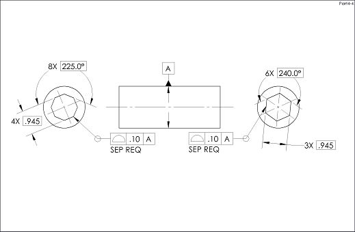
One end of a part is hexagonal—left end: called datum feature A, dimensioned with basic angle, basic size across the flats, basic size across opposite corners and an all-around datumless profile.

The opposite end: right end: profile all around to A primary. (same as the left end: everything else is shown basic).

Questions:
How to relax the clocking between the hexagonal side of the part and octagonal one?
We have some arguments that SIM REQT added under the octagonal all-around profile will only brake the mutual relationship between the eight sides of the octagon, but won’t accomplish anything about relative rotation between hex and octagonal shape.

How to make the octogonal shape to freely rotate about its centroid?
 
 https://files.engineering.com/getfile.aspx?folder=1eca0cbe-647a-4ceb-a2d3-5cd0862ca838&file=HO.JPG
Replies continue below

Recommended for you

gabimoang,

Why would you think that SIM REQ would BREAK the relationship between any features? Perhaps you're thinking of SEP REQ. It is my understanding that since all 8 sides are controlled by an all over profile tolerance that the addition of SEP REQ would disconnect the relationship of those 8 sides to other features on the part - not between the 8 sides themselves.

Unfortunately for your situation, since the datum feature A is the all-around profile of the hexagonal feature this would be similar to the linear extruded shape shown in Fig. 4-3 which constrains all DOF but one - I don't think simply applying "SEP REQ" would allow the octagonal profile to rotate OR translate in relation to the hexagonal profile since the hexagonal profile is the referenced datum feature - SEP REQ allows features to rotate/translate in relation to each other, NOT the referenced datum feature (ie: does not remove DOF constrained by the DRF).

A possibility might be somehow creating a datum from the primary datum feature which does not constrain this DOF - for example the inscribed circle formed by the sides of the hexagon. I hate to even mention it as it is always a point of contention, but another possibility is a custom DRF to allow rotation about the hexagonal feature's primary axis.
 
chez311,

chez311 said:
I don't think simply applying "SEP REQ" would allow the octagonal profile to rotate OR translate in relation to the hexagonal profile since the hexagonal profile is the referenced datum feature - SEP REQ allows features to rotate/translate in relation to each other, NOT the referenced datum feature (ie: does not remove DOF constrained by the DRF).

Could you, please, explain this issue in more details. Don't get what you mean. Why SEP REQT does not take care of the job-allowing the 8 side shape to rotate freely?
 
Kedu,

If you read the applicable section of 4.19 regarding simultaneous requirements you will see that the exact verbiage is "In a simultaneous requirement there is no translation or rotation between the datum reference frames of the included geometric tolerances thus creating a single pattern." Simultaneous requirements, and separate requirements, does not involve the addition/removal of DOF constraint relative to the referenced datum features but instead between separate features/patterns which share a common DRF. In this case, one the feature of interest (hexagonal shape) is also the datum feature which is referenced in the DRF of the other feature (octagonal shape) - it is NOT simultaneous requirements which constrains rotation/translation but the standard rules regarding datum feature definition and DOF constraint (aforementioned "linear extruded shape" constraining 5 DOF), therefore the specification of separate requirements does not free up any of these DOF. The only way I see to do that is to somehow modify how the datum itself is defined and I mentioned two methods.

Additionally simultaneous/separate requirements do not apply in this case because the two features do not share a common DRF. The hexagonal shape is controlled through datumless profile which then makes up datum feature A. The octagonal shape is controlled through profile to [A].
 
Looks like a job for custom DRF :)

"For every expert there is an equal and opposite expert"
Arthur C. Clarke Profiles of the future

 
Or just write a note describing the way the designer/engineer imagines this being used.
 
gabimoang,

You can add a datum to one side of the hex, and apply a very sloppy angle tolerance to the octagon.

--
JHG
 
CH,
I tend to agree which is why I mentioned it in my initial reply. The more it comes up the more I see some select cases where customized DRF may be useful - not because it more accurately mimics the mating/functional condition of the part but because it allows more freedom for manufacturing ie: when assembled the hex may constrain all those 5 DOF but the initial rotational clocking of the features (determined prior to assembly in manufacturing) which reference it is not important.

drawoh,
It sounds like the intent is only to allow rotation. Wouldn't that allow rotation and translation?
 
I think what drawoh suggested is OK but really, just add a note saying the octagon can rotate in respect to the hexagon.

----------------------------------------

The Help for this program was created in Windows Help format, which depends on a feature that isn't included in this version of Windows.
 
chez311,

You need to apply some sort of composite feature control. You need controls that prevent translation, and one that permits lots of rotation.

--
JHG
 
drawoh,

I'm open to the idea of a composite control that does this but I'm coming up blank on something that would allow rotation of a planar feature (or a complex feature made up of planar features) while restricting translation. Seems to me that traditional controls either restrict both or allow both - at least for planar features. Any chance you could provide an example of what you're thinking of?

I'll be honest, if one is opposed to utilizing a custom DRF I sort of like my initial suggestion of utilizing an inscribed circle or cylinder as a datum. Anyone have thoughts on that?
 
chez311, CheckerHater,

Let's assume that the hexagonal and octagonal features are surfaces extruded in the z-axis direction. For the profile tolerance applied to the eight surfaces of the octagonal feature, presumably you would propose a customized DRF of |A[u,v,x,y]|, where datum feature A is the six surfaces of the hexagonal feature.

Imagine a slightly modified scenario where the hexagonal feature still has six equal angles, but one of the sides is at a different distance from the "center" than the other five. Would you consider the same customized DRF approach viable in this case?


I'll be honest, if one is opposed to utilizing a custom DRF I sort of like my initial suggestion of utilizing an inscribed circle or cylinder as a datum. Anyone have thoughts on that?

Using the inscribed cylinder of the hexagonal feature to establish a datum axis sounds workable. Alternately, a position tolerance could be applied to the inscribed cylinder of the octagonal feature.

pylfrm
 
pylfrm,

I think I see what you're getting at but I don't really have an answer to that unfortunately. If I'm not mistaken, what you're trying to determine is if we remove the rotational DOF, about what axis is rotation allowed - am I correct? This axis is clear and easy to visualize for a regular polygon but is perhaps not so for the situation you described or anything other than a regular polygon as the method to determine this could vary without explicit guidance from the standard (centroid? circumscribed/inscribed circle? other method?).

If we're being fair though, the same could be said for Fig. 4-46 where a square (again - regular polygon) is intended to only constrain [x,y] translation and allow [w] rotation. Thus again I guess arises another issue with custom DRF - we are given a potentially useful method without all the proper tools to implement it.


I'm glad you think the inscribed circle/cylinder is viable. I agree it could be applied either way - to establish a datum axis for the hexagonal feature or for a position tolerance on the octagonal feature. Unless it is critical to account for the influence of variations away from the center of each side as this is ultimately where an inscribed circle/cylinder would contact (this could be minimized with a sufficiently tight profile tolerance) I would say this is my first choice - unless perhaps someone can present an example of the "composite feature control" mentioned.

Alternately, as a last choice, some other round/cylindrical feature could be chosen as a datum feature and both hexagonal/octagonal profiles could be held to it with SEP REQT applied.
 
If I'm not mistaken, what you're trying to determine is if we remove the rotational DOF, about what axis is rotation allowed - am I correct? This axis is clear and easy to visualize for a regular polygon but is perhaps not so for the situation you described or anything other than a regular polygon as the method to determine this could vary without explicit guidance from the standard (centroid? circumscribed/inscribed circle? other method?).

That's basically what I'm getting at. If [w] is unconstrained, [x,y] can only be constrained on a single line. If the datum feature has rotational symmetry, it's certainly easy to assume that the symmetry axis should coincide with that line. The text of ASME Y14.5-2009 doesn't actually specify this though.

I think the idea of constraining [x] before [v,w], [y] before [u,w], or [z] before [u,v] is generally rather questionable without a clarifying note.


How to relax the clocking between the hexagonal side of the part and octagonal one?

If there are no basic dimensions (implied or otherwise) linking the clocking of one feature to the other, is there even anything to relax?


pylfrm
 
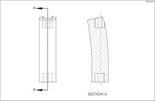
The longer I was looking at OP picture, the stronger was the feeling that hex is not really a datum.

In fact, it was referencing datum A somewhere else.

So, maybe the whole picture looked somehow like that?

Hex_to_Oct_zoiati.jpg


"For every expert there is an equal and opposite expert"
Arthur C. Clarke Profiles of the future
 
CH,
If the OD is datum feature A, as you proposed, wouldn’t the functional approach / GD&T philosophy be altered? As far as I can understand from the Op’s picture, the OD is just sitting in the air and has no mating relationship.
If OD is the datum feature A, then SEP REQT wound do the job, but would be too easy for a question posted on the forum[bigsmile]

I think the hex is datum feature A.
 
greenimi, would you say, this is the appropriate way to produce the part, based on the assumption that OD is irrelevant?

Datums_mibqdu.jpg


This is why overuse of the word "functional" makes me sick.

"For every expert there is an equal and opposite expert"
Arthur C. Clarke Profiles of the future
 
CheckerHater said:
greenimi, would you say, this is the appropriate way to produce the part, based on the assumption that OD is irrelevant?

No, I did not say that. The OD would be the controlled (deriven feature and not the driving one) and is to be controlled to the datum feature A --the hex--within some tolerance. This relationship between the hex (datum feature A) and the OD is not shown in the print because (I assume) is not part of the OP's concern.

My point is that, if we are introducting a non-functional feature/ non-mating feature, are we deviating from the "known" / per the book philosophy / reccomanded approach to use the mating approach?


My point is, we don't know what "functional" is.

Imagine piece of pipe threaded from both ends. The "function" is to screw one end somewhere and then screw something else to another end.
Is controlling one threaded end wrt the other functional?

Thread generally makes bad datum feature. Now imagine some 30 ft long drill pipe. Believe me, it will not function unless both treads are produced with respect to OD. The "functional" will be requirement that produces good part. Yet another simple thing being forgotten.

"For every expert there is an equal and opposite expert"
Arthur C. Clarke Profiles of the future

 
CH,
I kind of agree that sometimes this “functional” word is misused and again “just sometimes” functional approach is pushing the line of absurdity.
And I am all for making and defining the drawing to the most user friendly callouts.

On this specific example, let me ask you a couple of additional questions about your proposal:

You have the OD datum feature A—keep it as is (for the sake of this discussion)

For the hex, why the hex could not be defined with 3x size (.945±.xxx) and tolerance across the flats and 3x position to A. If my approach is valid, then what about the angle 240 degrees in your picture: should be basic or no? Just asking. Or should be replaced with 60 degrees basic or direct toleranced?

In other words, I am asking how to define (size/ form/ orientation/location) a hex with plus-minus dimensions?
 
Status
Not open for further replies.

Part and Inventory Search

Sponsor