Continue to Site

Eng-Tips is the largest engineering community on the Internet

Intelligent Work Forums for Engineering Professionals

  • Congratulations SDETERS on being selected by the Eng-Tips community for having the most helpful posts in the forums last week. Way to Go!

Nominal versus mean on MBD

Status
Not open for further replies.

Kedu

Mechanical
May 9, 2017
193
MBD environment and settings

Should we model at "the nominal" or at "the mean"?
Looks like design-inspection preference is "the nominal" and manufacturing is "the mean".
Creating a derivative for manufacturing looks like it is NOT a GREAT solution (could be an OKAY one however) due to the translation issues and validation problems.
Any comments?
How would YOU solve it?

 
Replies continue below

Recommended for you

It all depends. For castings it may be several percent over the maximum dimensions so the pattern is correct. For most CNC, just under the max to allow cleanup of nicks or tool chatter.

Manufacturing most always creates its own derivatives, at least by specifying the raw stock size.
 
Nominal.
In cases of limits and fits for features of size modeling to mean will prevent you from specifying the nominal dimension with the asymmetric tolerance, from technical reasons, unless you do a workaround like a fake dimension. Then you will change the dimension structure & loose the design intent communication.
 
Burunduk,
I think in MBD fakeing a dimension is not allowed, so I guess the mean is not really an option for limits and fits, unilateral and unequal tolerancing.
Not sure however about model derivatives and how to check the differences between the original and the derivative
 
Kedu,

What do you mean by nominal versus mean?

The whole point of MBD is that there are no dimensions on the drawing. Nominal dimensions come from the model. The profile tolerance on your drawing note or (somehow) on your PO provide acceptable variance from that nominal.

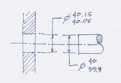
Nominal and mean kick in when you call up limits and fits on your CAD drawing thus...

NominalAndMean22_kqov3z.png

If I had used CAD and I had sent my CAD models to the shop, they would need to know how I modelled my features. Are the shaft and hole both modelled to [⌀]40mm? Perhaps the shaft has been modelled to [⌀]39.95. Perhaps both pieces are modelled at MMC! These distinctions are meaningless if the thing is hand drawn, or modelled but not dimensioned.

How will the fabricator know you needed this thing to be precise?

--
JHG
 
MBD has dimensions and tolerances associated with every feature, part of the "Definition". Manufacturing can examine how the features are modeled and the related tolerances; MBD just ensures that the information is directly associated with the surfaces. Trying to pass through an underdefined or unexamined MBD engineering model as the CAM model to the shop floor is problematic.
 
I think the confusion is coming from those statements:

Which one would you chose if design wants something and manufacturing wants something else AND there is no way to verifiy, validate, certify, authorize and authenticate any of the transitions and translations between those files? Original source vesus derivatives, how would you confidently say "they are the same"?


6.1 GENERAL
Models represent ideal geometric constructs; that is, perfect dimensionality and shape aspect of the part geometry are assumed. Parts shall be modeled at a specified
dimensional condition(s); for example, minimum, maximum, or mean. The dimensional condition(s) shall be specified in one or more notes or in a referenced document.


9.2.3 Size Dimensions
A displayed feature of size dimension shall always
include a tolerance.
(a) Size Dimension and Annotated Model Agreement. A size dimension shall agree with the queried model value for the same feature when the model value is rounded to the same number of decimal places. This agreement shall meet one of the following requirements, depending on the tolerance expression used.
(1) Bilateral or Unilateral Tolerance. The displayed size dimension shall equal the resolved model value.
(2) Limit Dimensions. The resolved model value shall equal one of the limit dimensions, or a value within the displayed range of limits.
(3) Dimensions With Plus/Plus or Minus/Minus Tolerances. The resolved model value shall not be within the displayed range of limits.


It would have been easy enough to specify offset surfaces to represent material limits with solid geometry representing the nominal.
 
Status
Not open for further replies.

Part and Inventory Search

Sponsor