Eng-Tips is the largest engineering community on the Internet

Intelligent Work Forums for Engineering Professionals

Datum Targets in MBD 1

Status
Not open for further replies.

Mech1595

Mechanical
Oct 16, 2023
29
0
1
US
All,

Had an interesting one related to Datum Targets come through recently, and was hoping you could provide some insight.
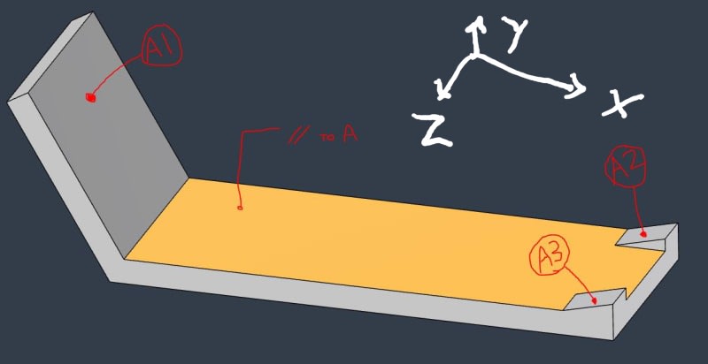
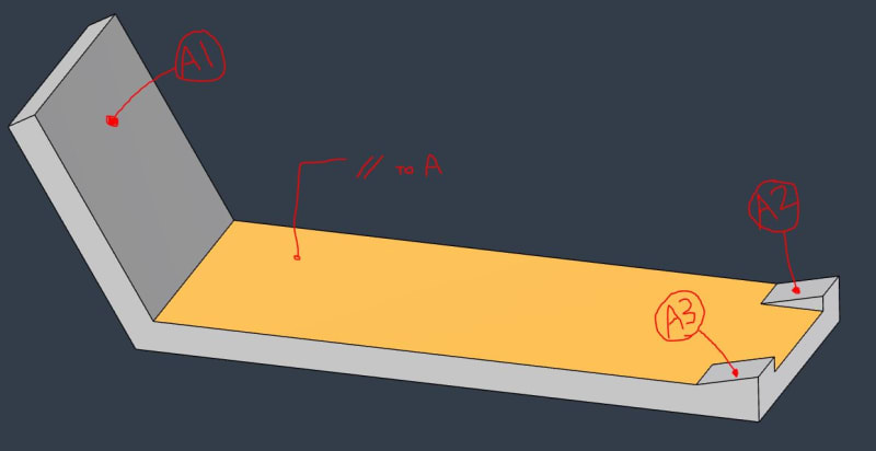
Below is a simplified example of the component. The customer has Datum A defined with (3) Datum Target Points: A1, A2, A3.
They also have Parallelism to [A] specified on the yellow surface.

Here's where I'm lost:
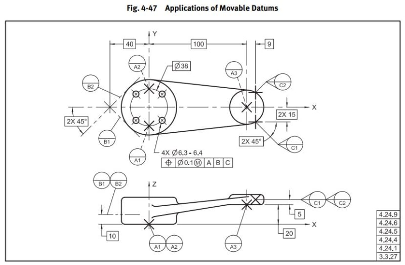
Their design intent is for Datum Plane A to be parallel to the yellow surface, but I don't understand how it could be with this info. I looked through Y14.5-2009 and found Fig 4-47 as an example, but they have the Datum A targets offset with the Basic [20]. This component is defined with MBD, with no basic offset like Fig. 4-47, just WCS coordinates for the Datum Targets.
It's also located way out in vehicle position, and not aligned to the WCS in a way that any of the planes (XY, XZ, YZ) would match intended Datum Plane A orientation.
Is this valid? If so, what is the mechanism driving Datum A to be oriented as they suggest? Would Datum A not just be coincident with the (3) Datum Target Points?


Datum_Targets_jltvd3.jpg


4-47_woagwx.jpg
 
Replies continue below

Recommended for you

Correct, they are Target Points, and my crude mouse-scribbled screenshot is definitely not to standard.

Pmarc, yes I did see that figure but wasn't quite sure how to apply it to this situation.
 
The OP is an unreliable narrator; as you indicate, the symbols are inaccurate. Points require an X, not a dot.

More than that, 3 points in that configuration aren't a stable support; that can only happen if they are areas.

The alternative to using them this way is to identify them individually and using something like [A-B-C] in the datum reference portion of the feature control frame.

At this point the analysis trail is dead. There is no given purpose for selecting those surfaces and no given expected result. I'd await an installation drawing and related component drawings, but this simplified construction leaves no useful information in that direction.

Edit: For f's sake, the OP posted while I was typing.
 
3DDave,

I explicitly identified these at Datum Target Points in the OP:

Mech1595 said:
The customer has Datum A defined with (3) Datum Target Points: A1, A2, A3.

I didn't realize I also had to specify that the simplified hand-drawn example with literally zero valid Y14.5 elements was for reference only, but here we are. Sorry for the confusion.
 
Hi, Mech1595:

Those A1, A2 and A3 in your original post are not datum targets. They are just plain labels for 3 datum features (flat surfaces) that you can reference in your feature control frames any ways you want.

Best regards,

Alex
 
Mech1595,

Then that datum scheme cannot work under any circumstance as it absolutely fails in every way to constrain the part.

I gave you the benefit of the doubt and that was clearly an error on my part. I won't do that in the future.
 
Regarding the capabilities of datum feature A as defined by the three (incorrectly sketched) datum target points to constrain the part; as a primary datum feature, its relation to the datum reference frame is established by 3 spherical-tip pins, arranged per the basic coordinate distances and normal to the corresponding surfaces. Those would form the datum feature simulator. This inspection set up would constrain 4 degrees of freedom. The DOF that will be constrained are 'X', 'u' (the rotation about 'X'), 'Y', and 'v' (the rotation about 'Y').

Datum_Targets_jltvd3_gbmg34.jpg


For the required orientation control limiting the tilt of the yellow surface, there would need to be an additional degree of freedom constraint that is not provided by A alone - it is 'w' (the rotation about Z). So in that sense I agree with 3DDave that for the shown scheme as it is, the 3 points are not a stable support to fully control the orientation of the yellow surface. This could be handled by an additional datum reference.

Whatever datum references solution is chosen, it should reflect how the degrees of freedom are arrested in the actual use application of the part.
 
3 points do not constrain 4 degrees of freedom. This does not constrain in rotation about Y. Because of the arrangement of the surfaces it ties rotation about X into rotation about Y. It also couples translation in X to translation in Y, varying in amplitude over the part.
 
3DDave,
Once the simulator for datum A (the 3 spherical tip pins) is in contact with the part, would you be able to rotate the part only around Y (and not any other axis) without losing contact at any of the pins? If not, that rotation is constrained. Rotation only about X does not look possible at all without loosing contact, either. "It also couples translation in X to translation in Y, varying in amplitude over the part" actually describes rotation about Z and not pure translation in either X or Y.
 
I wish you knew enough about transformation matrices to have this discussion. Instead I'd suggest you get some cardboard and some dowels and stick the dowels into a piece of foam to mock up the datum targets. Use the cardboard to make a model similar to the part shown.

"not pure translation in either X or Y" is what "couples translation in X to translation in Y" means. I clearly said it; was that not understood and you thought it an original idea to say the same thing?

Coupling happens when the degrees of freedom are not orthogonal, a term you should be familiar with from linear algebra where they taught about transformation matrices and augmented transformation matrices.
 
3DDave,
I'm not sure that datum related degrees of freedom should be over-analyzed this way.
Suppose you have a 120° arc (partial cylinder) as a primary datum feature. The tangential-horizontal direction is X, the radial-vertical is Y. How many degrees of freedom are constrained? Are X and Y not constrained because the part can slide in tangential directions that combine both X and Y? According to your approach they would be considered unconstrained.
 
Oh look, the parade of unrelated hypotheticals has begun. This is three POINTS.

It would be axial movement, not tangential, but that's off topic. Draw a picture to see what it is you are referring to.
Figured out the stupid puzzle. Love stupid word games.

The rotation of a cylindrical feature in a cylindrical datum feature simulator has a nominally constant instantaneous center and such motion means that the radii to any point on the part to that instantaneous center remain constant. There is no notion of direction axes so they simply rotate with the part and cannot be resolved into any components.

In this case the instantaneous center moves continuously and is not confined in orientation relative to the datum points. The datum points serve as a basis to determine where that axis is. Taking the cross product of vectors between two pairs of points creates a vector normal to the plane and therefore a measurement direction.

In the case of the cylinder an infinite number of vectors normal to the axis of rotation can be created; there is nothing to distinguish them.
 
The issue with your explanation regarding the partial cylinder with a fixed center is that a partial cylinder with an arc of less than 180° used as a datum feature won’t provide a central axis as a datum. It has no Unrelated Actual Mating Envelope to obtain the axis from. Therefore, you don’t get an axis to link rotating planes to, to rotate the reference system with the part, as you want, during the sliding of the datum feature on the simulator. Once a coordinate system origin is set, sliding the arc would result in simultaneous translation in two coordinates. And if your analysis from the other case was correct, those would represent unconstrained degrees of freedom. But as expected, you refuse to apply the same reasoning from earlier to a simpler case, where the conclusion might be perceived as more controversial.
 
The mating cylinder surface provides the axis; every movement of the mating surface is about a single axis.

If there is no axis to begin with, then how do you know it's a partial cylinder? How is that partial cylinder created?

When you took your kinematics classes did they not discuss instantaneous centers for determining the actions and accelerations of links in linkages? That's a basis for solid body dynamics. It is pretty basic stuff for engineers.

Can you go back to proving that 3 points are going to rigidly lock in 4 degrees of freedom with some sort of free body diagram?
 
Do your own free body diagrams.
You can consider reaction forces and moments that keep the part static as representing the applied constraints.
 
If I am so new at this how did my request to have "geometric dimensioning" removed from the body of the Y14.5-2009 standard happen? I submitted that for the public review draft comments in 2008 or so, about 16 years ago. It was there in the second version of Y14.5 I worked with, the ASME 14.5M-1994, 1.1.1.

I do believe in proof.

I certainly did not say that a datum feature axis was involved, just an axis, like any other discussion of a cylindrical bearing, whether 120º or not.

Can you go back to proving that 3 points are going to rigidly lock in 4 degrees of freedom with some sort of free body diagram? That was your contention.

Edit: Removed references to deleted post.
 
B said:
Do your own free body diagrams

I have. Plenty of them. That's how I know you are wrong. Wasn't there some course you had on design of machine elements? Kinematics? Design of linkages? Have you forgotten them all?

Can you go back to proving that 3 points are going to rigidly lock in 4 degrees of freedom with some sort of free body diagram? That was your contention.

Make a CAD model in the kinematics package and use those 3 points to mate to and see how the software allows you to drag the part. You'll find it has 3 degrees of freedom; 2 rotation and 1 translation.
 
"nothing else" is a stretch. You should have taken the comments about your attitude to your attention but you keep at it. Possibly you will learn the lesson in your work place, the hard way.

As I said, do your own free body diagrams.
 
Prove that 3 points are going to rigidly lock in 4 degrees of freedom.

If you haven't got the necessary background, please say so.
 
3DDave & Burunduk,

It looks like the apparent peace between the two of you, that I asked for in this recent thread and which you have respected since then (thank you for that!), couldn't last forever. So let me repeat my request and, at the same time, quote the Posting section of the Eng-Tips Posting Policies so that you can both identify the rules/expectations that you have been struggling to meet and to display potential consequences of that:

Posting
Commercial and/or recruiting "spam" will not be tolerated in the forums. Our forums are member-policed via the forums' "Red-Flag" utility. Offending posters will be dealt with sternly not only by the management of this site, but also face possible retaliation by the members of this web community (we exert no control over our members and in no way encourage this kind of activity).

The following activities can result in deletion of posts, deletion of threads and/or restriction of further site usage. Members who engage in any of the following activities may be red flagged by the membership. Management of this site does not read any post unless it has been red flagged by a member. In no particular order, here are some common offenses:
[ul]
[li]Selling[/li]
[li]Recruiting[/li]
[li]Student Posting[/li]
[li]Profanity[/li]
[li]Cross Posting[/li]
[li]Tack-On Posting. If you have a new question, start a new thread.[/li]
[li]Arguing in an Unprofessional Manner[/li]
[li]Posting of Personal Information[/li]
[li]Posting Anything Illegal (including hacking, cracking, passwords, etc.)[/li]
[li]Defamatory Posting[/li]
[li]Shill Posting, or posting made at the behest of a company[/li]
[li]Leeching (members posting only questions, and never helping others)[/li]
[li]Irritating Other Members[/li]
[/ul]

On the other hand, members are expected to:
[ul]
[li]Search Google, Previous Posts, and FAQs Prior to Posting.[/li]
[li]Write Intelligent Questions And Use Descriptive Subject Lines[/li]
[li]Thank Other Members For Help Received & Click the "Thank (member) For This Valuable Post!" Link[/li]
[li]Help Other Members[/li]
[li]Red Flag Offensive Posts[/li]
[li]Be Professional[/li]
[/ul]
 
Status
Not open for further replies.
Back
Top