All,
Had an interesting one related to Datum Targets come through recently, and was hoping you could provide some insight.
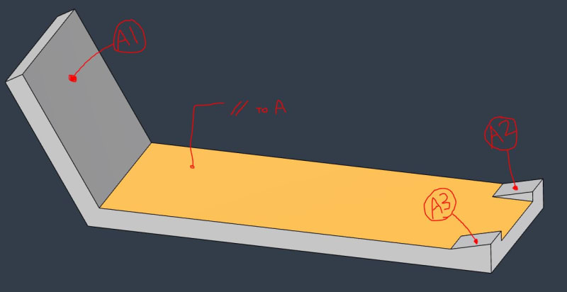
Below is a simplified example of the component. The customer has Datum A defined with (3) Datum Target Points: A1, A2, A3.
They also have Parallelism to [A] specified on the yellow surface.
Here's where I'm lost:
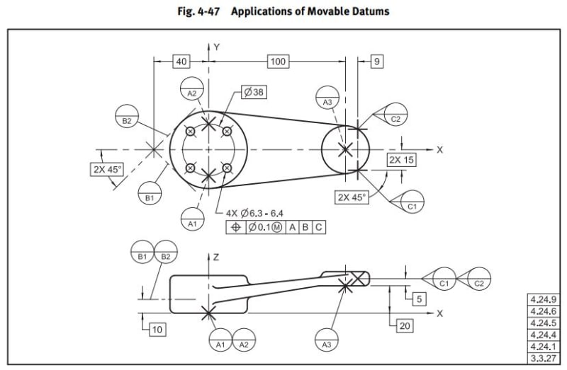
Their design intent is for Datum Plane A to be parallel to the yellow surface, but I don't understand how it could be with this info. I looked through Y14.5-2009 and found Fig 4-47 as an example, but they have the Datum A targets offset with the Basic [20]. This component is defined with MBD, with no basic offset like Fig. 4-47, just WCS coordinates for the Datum Targets.
It's also located way out in vehicle position, and not aligned to the WCS in a way that any of the planes (XY, XZ, YZ) would match intended Datum Plane A orientation.
Is this valid? If so, what is the mechanism driving Datum A to be oriented as they suggest? Would Datum A not just be coincident with the (3) Datum Target Points?


