Continue to Site

Eng-Tips is the largest engineering community on the Internet

Intelligent Work Forums for Engineering Professionals

  • Congratulations KootK on being selected by the Eng-Tips community for having the most helpful posts in the forums last week. Way to Go!

Datum Targets in MBD 1

Status
Not open for further replies.

Mech1595

Mechanical
Oct 16, 2023
32
All,

Had an interesting one related to Datum Targets come through recently, and was hoping you could provide some insight.
Below is a simplified example of the component. The customer has Datum A defined with (3) Datum Target Points: A1, A2, A3.
They also have Parallelism to [A] specified on the yellow surface.

Here's where I'm lost:
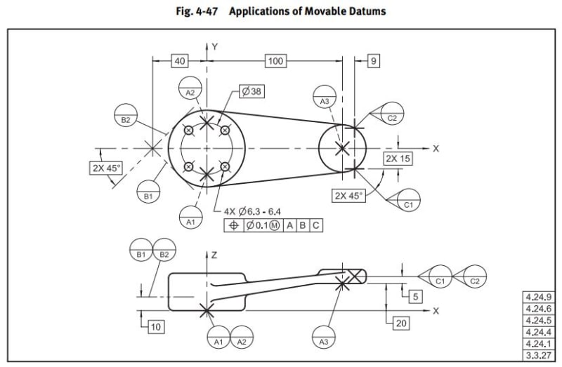
Their design intent is for Datum Plane A to be parallel to the yellow surface, but I don't understand how it could be with this info. I looked through Y14.5-2009 and found Fig 4-47 as an example, but they have the Datum A targets offset with the Basic [20]. This component is defined with MBD, with no basic offset like Fig. 4-47, just WCS coordinates for the Datum Targets.
It's also located way out in vehicle position, and not aligned to the WCS in a way that any of the planes (XY, XZ, YZ) would match intended Datum Plane A orientation.
Is this valid? If so, what is the mechanism driving Datum A to be oriented as they suggest? Would Datum A not just be coincident with the (3) Datum Target Points?
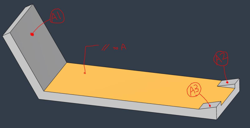
Datum_Targets_jltvd3.jpg


4-47_woagwx.jpg
 
Replies continue below

Recommended for you

pmarc,

Since you are here, care to participate in examining if 3 points in this case control 4 degrees of freedom?

 
3DDave,
If you really want an answer, then in order to draw and analyze a free body diagram, you need to define the location, direction and magnitude of the external forces and moments against which the reactions will act.

I could find the direction and location of an external force that would cause this structure to be in equilibrium when supported on 3 points.

On the other hand, I could describe a structure, such as a part shaped like the letter "L" standing upside down with a long horizontal leg, where the end it stands on is a flat surface with a small area, and the structure would not be stable due to its own weight. Does this mean that a flat surface cannot reliably constrain 3 degrees of freedom? The connection is weak.

The analysis of degrees of freedom in geometric tolerances is not equivalent to solving statics problems and is not dependent on a bad or good design. That is up to the design engineer to solve.
 
For kinematics one does not need to know the external forces to make the diagram. In this case one needs to show there is only a single nominal solution to capturing degrees of rotation that are not perpendicular to the toleranced plane in order to determine a basis for an angularity tolerance.

"I could find the direction and location of an external force that would cause this structure to be in equilibrium when supported on 3 points."

The same could be said if there was a single target point. That also is not a solution.

Three points cannot constrain 4 degrees of freedom.
 
I didn't provide whatever you expect to see in a kinematic free body diagram of the part, but at least I detailed at 14 Sep 24 10:58 exactly how many and which degrees of freedom I think are constrained by datum feature A designated by the 3 datum target points. To do that I added a coordinate system to OP's graphic and spelled out the applicable constraints as I understand them.

Your input on this on the other hand, has been completely unclear;

"Then that datum scheme cannot work under any circumstance as it absolutely fails in every way to constrain the part."

"3 points do not constrain 4 degrees of freedom. This does not constrain in rotation about Y. Because of the arrangement of the surfaces it ties rotation about X into rotation about Y. It also couples translation in X to translation in Y, varying in amplitude over the part."

"Make a CAD model in the kinematics package and use those 3 points to mate to and see how the software allows you to drag the part. You'll find it has 3 degrees of freedom; 2 rotation and 1 translation."

Those statements do not add up to something coherent. Can you make your own figure of the part in question showing the directions of the constraints and their labels?
 
"exactly how many and which degrees of freedom I think are constrained by datum feature A designated by the 3 datum target points"

"its relation to the datum reference frame is established by 3 spherical-tip pins, arranged per the basic coordinate distances and normal to the corresponding surfaces. Those would form the datum feature simulator. This inspection set up would constrain 4 degrees of freedom."

Technically, spherical-tip pins cannot be normal to surfaces, they can only be tangent to them.

In this example, or any other example, three of them cannot constrain 4 degrees of freedom. They cannot even necessarily constrain 3 degrees of freedom in cases where the datum target points are colinear.

The three points in the original post lie on a plane. Because they are on a plane a circle in that plane can be constructed that passes through all three points. The center of that circle with that plane define an axis. The part can be rotated about that axis by rocking the part to maintain contact at the three points. That is unconstrained coupled rotation about Y and X shown in the 14 Sep 24 10:58 diagram.

From the side view, construct surface normals at the location where the datum target points lie on the part surface, normal to the respective surface. They will intersect at a point a finite distance from each surface. This is the instantaneous center of rotation. This allows unconstrained rotation about the Z axis shown in the 14 Sep 24 10:58 diagram.

That totals 3 unconstrained degrees of freedom. Since all the Cartesian coordinates for points elsewhere on the part change relative to the datum target points when the part is rotated about the X, Y, and Z axes, as allowed by these 3 datum target points, it's not clear that one could say the locations of the surfaces are fully constrained either.
 
3DDave said:
Technically, spherical-tip pins cannot be normal to surfaces, they can only be tangent to them.

I meant the pins are normal, not their tips. Although I agree it doesn't matter as the contact forces will be normal to the respective surfaces anyway.

3DDave said:
That totals 3 unconstrained degrees of freedom. Since all the Cartesian coordinates for points elsewhere on the part change relative to the datum target points when the part is rotated about the X, Y, and Z axes, as allowed by these 3 datum target points, it's not clear that one could say the locations of the surfaces are fully constrained either

So does that mean zero degrees of freedom constrained? All 3 rotations and all 3 translations kept free?

Just for the record recall I didn't say the orientation was fully constrained either:
"So in that sense I agree with 3DDave that for the shown scheme as it is, the 3 points are not a stable support to fully control the orientation of the yellow surface. This could be handled by an additional datum reference." (14 Sep 24 10:58)
 
"Just for the record recall I didn't say the orientation was fully constrained either:"

Just for the record recall I didn't claim you did.

I disputed your claim that 4 degrees of freedom were constrained and have shown why your claim is incorrect.

When I referred to "it's not clear that one could say the locations of the surfaces are fully constrained either" I was, in a context which is important, referring to my own analysis, having nothing to do with the 14 Sep 24 10:58 claim.
 
I didn't say you claim that I said the orientation is stable, either. I was just emphasizing that I also say it is not.

Perhaps it's not 4 degrees of freedom, you may be right about that.

So is it a zero degrees of freedom constraint or not? That was my question.
 
To the rest of the Usual Suspects, what is your answer to Burunduk - is it a zero degrees of freedom constraint or not?
 
Asking the others is not a bad idea either, but you were asked as the one who provided the insight. You provided a logical analysis that takes into account things I didn’t consider, and I’m sure these things aren’t trivial to many others here either.
But for some reason, you don’t want to write down the conclusion from your analysis. What are you afraid of?

Both the person asking the question and anyone learning from this discussion, including myself, could benefit from the conclusion you're not revealing.

This is a discussion forum on a complex topic, and even if you say something controversial, that's fine.
 
I have previously said it is important that people learn to answer their own problems by providing enough to figure it out.

"you may be right about that" suggests you still aren't sure.
 
Fine, I will state my interpretation of the required solution from your logic since you won't; If we adopt your method of analyzing this then the unavoidable solution must be that this 3 points contact doesn't constrain any degrees of freedom.

Here is why - you clearly described rotation about 3 axes, one translation is free without doubt in the direction with nothing in the way (Z axis in the modified OP's image I posted), then there are two more translations to decide about. Also, "Since all the Cartesian coordinates for points elsewhere on the part change relative to the datum target points...""...it's not clear that one could say the locations of the surfaces are fully constrained either" and you can't be half-pregnant, degrees of freedom are either constrained or not (especially where there is no shift), then the remaining two translations are also free.

Then, since an interface that doesn't constrain any degrees of freedom is in conflict with any other acceptable theory on this matter such as ISO's invariance classes, something must be flawed with your analysis.
 
This is a specifically identified ASME Y14.5-2009 problem so ISO invariance classes have no bearing.

You are so close, but remain too argumentative to understand the particular problem with this case.

If you could confront your conjecture that 4 degrees of freedom were constrained that would be a start.

I have demonstrated that the datum target points for this part are unsuitable for constraint in order to validate a parallelism or angularity tolerance. That is sufficient.
 
3DDave said:
This is a specifically identified ASME Y14.5-2009 problem so ISO invariance classes have no bearing.

It has a lot of bearing.
Fig. 4-3 Constrained Degrees of Freedom for Primary Datum Features, often treated as a general categorization, is essentially the same thing as ISO's invariance classes, minus the helical case. Bill Tandler's "Six Possible Datums" which you promoted here at one time is more of the same thing.

As I said, I'm no longer sure it can be said 4 DOF are constrained.
But as long as you are not explicit about the conclusion of your analysis and avoid answering how many degrees of freedom do get constrained, or is it indeed zero, your assessment can't be trusted as a valid one. Specifically because the natural conclusion from it (zero constraints), which you do not confirm or deny, contradicts acceptable conventions.

"unsuitable for constraint" is not a full answer. It is an answer that lacks any of the essential details when provided as part of a discussion on degrees of freedom in geometric tolerancing.
 
"As I said, I'm no longer sure it can be said 4 DOF are constrained."

Ok. What basis do you have for that doubt?
 
Separate issue:

Datum target point simulators for this thread example don't require the body of the spherical-end pin to have any particular orientation as long as their bodies don't interfere with the part. It could be a half-ball bearing brazed to a plate and not use a pin at all. The gage maker does need to ensure that the center of the sphere is on the normal vector to the nominal tangent surface located at the point of contact with the scalar magnitude for the offset from that point as close to the radius as the precision required for the gage.

A case for alignment of the pin body could be made for adjustable datum target point simulators, but that is not the need for this thread example and the motion could be managed other ways; a cylindrical pin body isn't the exclusive solution, just one of many.

For CMMs all this is out the window. There is no support structure for the mathematically defined contact. I wonder how many CMM operators use a physical probe that is the same size as would be used in a fixture.
 
3DDave said:
What basis do you have for that doubt?

In my thinking it has been that if you can't move the part directly at or around some direction, the relevant degree of freedom is not available. Meaning, if a datum feature simulator is any kind of obstacle to transformation in a given direction it locks that degree of freedom. For example, if you can't move the part to the right without making it slide up a slope then translation to the right is constrained.

Often it simplifies the DOF analysis and you can get away with it when eventually all translations and rotations end up constrained by the set of datum references in a given callout, but it might not be the best way to look at it. When not all DOF are arrested my approach may not provide exact understanding about how the part can move, or it may even give the wrong idea about how many DOF are actually constrained.

About the "Separate issue" - I agree and as I mentioned: "I agree it doesn't matter as the contact forces will be normal to the respective surfaces anyway." I also agree that it does matter for movable datum targets.
 
"if you can't move the part to the right without making it slide up a slope then translation to the right is constrained."

If the part can move while maintaining contact it isn't constrained. There is some handwaving required for MMC references as there is allowed movement, but only over a defined limited range.

Had there been a planar constraint on motion against sliding up, that would be true. The points would do that. In this case there is not, so they don't.

What makes this plain is that if you built that cardboard model you would be able to position that part onto the datum feature simulator in a large number of orientations without sliding. Turn it any number of ways and it will still contact those three points.
 
Forest for trees moment - had their been a primary planar reference that would be what would set the orientation for parallelism or angularity. The points would not participate. It would also be the case that the points would only remove one translational and one rotational degree of freedom as the contacts don't nominally constrain the final translational degree of freedom.
 
Status
Not open for further replies.

Part and Inventory Search

Sponsor