Continue to Site

Eng-Tips is the largest engineering community on the Internet

Intelligent Work Forums for Engineering Professionals

  • Congratulations SDETERS on being selected by the Eng-Tips community for having the most helpful posts in the forums last week. Way to Go!

Datum callout question 2

SeasonLee

Mechanical
Sep 15, 2008
917
I have some questions about this print, and I tried to make some changes as shown below. The reasons for making these changes are:
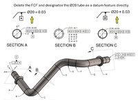
  • The common datum(A-B) is constructed after the individual feature is designated as the datum feature.
  • The existing DRF refers to the datum feature itself, normally we will consider it as a coaxial part, but here is a multiple skewed cylinder.
Datum callout.jpg
Do you agree with the changes on the datum callout? Please correct me if I am wrong here.
Thanks for your help.

Season
 
Last edited:
Replies continue below

Recommended for you

MMC (for qualfying the datum feature)......RMB (for referencing that datum feature) is also what the runout results at.
So are you saying you are OK with it just because it is illegal to reference a datum at MMB for runout? But the datum feature qualification could be RMB...
I am okay with both schemes shown in my replay above (green scheme and dark red scheme). I only have hard time to explain to people what is the logic behind the "combo". Why someone would want to have MMC (speaking of the green scheme) for qualifying the datum feature (in this case Ø zeo at MMC) and call this feature: datum feature A
AND THEN
when the 8mm hole is defined and datum feature A IS USED as primary someone would NOT use it as MMB but use it RMB.
What is the physical reality of such approach?

Or if someone would decide that the defintion of datum feature A is functionally RFS (considering Ø value bigger than zero) and when this newly created datum feature A is used to define the Ø8mm hole, we will use this A at MMB (modified at MMB).

Both cases are legal, but the explanation on why those "combo" are a good functional ideas.

Regarding runout, basically yes. I am okay with this inconsistencies because "the standard say so" (and runout cannot be modified neither MMC neither MMB). The runout is much easier to defend because again "is it's definition" per the book.
 
Last edited:
Just my humble opinion
It really depends it's fit form and function.
It is required for assembly
Or what is the designer want.

RMB or RFS is usually for precise or press Fitts.
MMC or MMB there wiggle room to assemble.

First case is more cost and there will be higher scrap rate.
The second will accept more parts and will assemble.

I love true position for holes. Only way to go.
Precision shafts where MMB is useless because
The tolerances are so tight. And precisely for
Where precision is required. To eliminate vibration, due to excessive runout or out of balance.

On assemblies where there no issue them MMB
OR MMC IS PERFECT
 
Actual minimum material envelope is created from inside the material. It "touches" the low points.

And so I make my point. The standard is written to maximize confusion.

LMC AND MMC are developed the exact same way, approaching the same material surface from opposite sides, but the description in the standard obliterates that similarity and fails to emphasize the difference.

Use INTERNAL MATERIAL SURFACE CONTACT ENVELOPE and EXTERNAL MATERIAL SURFACE CONTACT ENVELOPE.
 
"Both cases are legal, but the explanation on why those "combo" are a good functional ideas."

This is not a forum for explaining good functional ideas. This is a forum for legal language analysis without regard for applicability.

To understand good functional ideas one needs to examine the full tolerance loop and the range of variations and functional consequences of the applied tolerances and expected variations.

The way that General Dimensioning and Tolerancing (thanks for making that point Burunduk) is taught is to never evaluate those full tolerance loops because those are computationally expensive. And to never ever look at the functional consequences because those involve external functions - things like lubricant film thickness, stress and strain due to applied loads during assembly, cases were the "envelopes" do not represent actual mating conditions. Instead the instruction is how to add drawing decorations and make some primitive hole clearance calculations. Notice the lack of practical applications in any General Dimensioning and Tolerancing instruction, ones that start with a functional analysis and then back-calculate the controls necessary to meet them.

Most examples are geared to showing how to make life easier for CMM operators; some, like LMC and LMB, are nearly impossible for anyone without a CMM to evaluate if there is any form variation.
 
I only have hard time to explain to people what is the logic behind the "combo". Why someone would want to have MMC (speaking of the green scheme) for qualifying the datum feature (in this case Ø zeo at MMC) and call this feature: datum feature A
AND THEN
when the 8mm hole is defined and datum feature A IS USED as primary someone would NOT use it as MMB but use it RMB.
What is the physical reality of such approach?
Would you have an issue with A at RMB in the positional FCF for the 8 mm hole and instead of the datumless position of 0 at MMC for qualifying datum feature A, a Continuous Feature modifier aligning the two separate portions of the 16d9 diameter? It would mean exactly the same, only expressed by different symbols. What I am saying is that it is not necessarily a bad idea to have a size-adaptive tolerance for a datum feature of size and then calling out that datum feature at RMB. Even rule #1 alone is essentially a size-adaptive form tolerance (just having some "dia. whatever+/- whatever" is the same as having "dia. whatever+/- whatever " modified by circled "I" and then a derived median line straightness of 0 at MMC).
 

Part and Inventory Search

Sponsor