Continue to Site

Eng-Tips is the largest engineering community on the Internet

Intelligent Work Forums for Engineering Professionals

  • Congratulations SDETERS on being selected by the Eng-Tips community for having the most helpful posts in the forums last week. Way to Go!

Datum callout question 2

SeasonLee

Mechanical
Sep 15, 2008
917
I have some questions about this print, and I tried to make some changes as shown below. The reasons for making these changes are:
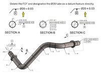
  • The common datum(A-B) is constructed after the individual feature is designated as the datum feature.
  • The existing DRF refers to the datum feature itself, normally we will consider it as a coaxial part, but here is a multiple skewed cylinder.
Datum callout.jpg
Do you agree with the changes on the datum callout? Please correct me if I am wrong here.
Thanks for your help.

Season
 
Last edited:
Replies continue below

Recommended for you

Yes it is , I am retired gear guy, I can
Sorry I was not trying to be facetious.
I am just trying to "provoke" people to give me more arguments (on both sides of the issue) that I can use in my REAL life (real issues) where the consequences of wrong decision (if you can even call it "wrong" decision) could be meaningful and then PITA will show up its ugly face :)

Basically what I am doing I am trying to improve my knowledge and talking with other people is the most effective way to do so.......The road to self knowledge often goes to other people.
OK no worries, I am biased, to my opinion which not popular. These new fcf mmc, mmb, rmb
Is geared for ASME certification and inspection.
It pushes toward to be inspected with CMM.
It does all the calculations.
For poor guy at his or her machine is difficult to measure. So expensive gaging is required.
Now that said if extremely high production it can be amortized by the quantity. I have quoting experience.. that makes it more ecomical.
But for R&D, or job shop work. It becomes expensive. because of low quantity
Cost becomes important.
To simplify manufacturing I would pinch the tolerance. And still meet the tolerance and the print.
Very simply m symble in the datum fcf allows a feature of size. No symbol in the datum is rmb so only mmc applies fcf
But I prefer runout because it simplifies the actual inspection.for the shafts.
Poking holes is mostly cnc mills, so it is machined and the precision is accomplished
By the precision of the machine, and the tooling.
And the setup. And generally it's held in the restrained condition for the rigidity.
On precision shafts it is tooled between centers and inspected between centers. Unless it is centerless ground.
 
Last edited:
OK no worries, I am biased, to my opinion which not popular. These new fcf mmc, mmb, rmb
Is geared for ASME certification and inspection.
It pushes toward to be inspected with CMM.
It does all the calculations.
For poor guy at his or her machine is difficult to measure. So expensive gaging is required.
Now that said if extremely high production it can be amortized by the quantity. I have quoting experience.. that makes it more ecomical.
But for R&D, or job shop work. It becomes expensive. because of low quantity
Cost becomes important.
To simplify manufacturing I would pinch the tolerance. And still meet the tolerance and the print.
Very simply m symble in the datum fcf allows a feature of size. No symbol in the datum is rmb so only mmc applies fcf
But I prefer runout because it simplifies the actual inspection.for the shafts.
Poking holes is mostly cnc mills, so it is machined and the precision is accomplished
By the precision of the machine, and the tooling.
And the setup. And generally it's held in the restrained condition for the rigidity.
On precision shafts it is tooled between centers and inspected between centers. Unless it is centerless ground.
Modifying tolerances to apply at MMC and datum features applied at MMB allow to make inspection simpler than when not using the circled M symbol. If the symbol is not used, then a tolerance applies regardless feature size and you have to measure the theoretical axis or center plane, or a derived median line/plane. Or the datum needs to be derived from a vise or a collet and you can't use fixed size component to hold the datum features during inspection and provide you the datum. As a simple example consider straightness applied to the diameter of a pin or shaft. If it is not specified with the MMC symbol, you need to spin it while sliding it between two opposing dial indicators and record the difference between their readings, or use a CMM. Which is "PITA" as you say (in my region a pita is a type of a flatbread). On the other hand, If the tolerance is applied at MMC by using the circled M symbol as supported by ASME, you can simply slide it into a ring gage or a sleeve with a fixed diameter representing the largest size pin/shaft with the max. allowed straightness deviation. And then as long as it fits, the straightness is good (but you also need to check that the diameter size is within limits by a caliper or micrometer).
 
Modifying tolerances to apply at MMC and datum features applied at MMB allow to make inspection simpler than when not using the circled M symbol. If the symbol is not used, then a tolerance applies regardless feature size and you have to measure the theoretical axis or center plane, or a derived median line/plane. Or the datum needs to be derived from a vise or a collet and you can't use fixed size component to hold the datum features during inspection and provide you the datum. As a simple example consider straightness applied to the diameter of a pin or shaft. If it is not specified with the MMC symbol, you need to spin it while sliding it between two opposing dial indicators and record the difference between their readings, or use a CMM. Which is "PITA" as you say (in my region a pita is a type of a flatbread). On the other hand, If the tolerance is applied at MMC by using the circled M symbol as supported by ASME, you can simply slide it into a ring gage or a sleeve with a fixed diameter representing the largest size pin/shaft with the max. allowed straightness deviation. And then as long as it fits, the straightness is good (but you also need to check that the diameter size is within limits by a caliper or micrometer).
Yes under stood. Pita is good bread lol.
In order to machine round stock in a cnc lathe
Must be chucked, collet, or between centers

In order to machine rectangular blocks in cnc mill
Must be in a vice, chuck or fixture.

So the point of that it has to be restrained because of the forces from machining.

for cylindrical grinding, between centers, or centerless
retangular block , a mag chuck is the preferred method. But a vacuum chuck for non magnetic material.

Now inspection normally can be held clamps or inspection fixture. And can be verified unrestrained condition.
Yet the bonus in fcf forgetting terms
Geometry characteristic symble the tolerance at mmc
Datum reference. At mmc
Is MMB and the bonus of high limit
And the MMC of geometric characteristic
Bonus depending on geometry.
Am I close?
 
I want to add unbiased opinion
I constantly pinch tolerances for manufacturing
For several reasons as I have noted in the other
Post.
Heat treat distortion
Tolerance stack up
For tooling purpose to achieve final dimensional results.
However sometimes I have to remember
The component has to meet the final print
At this point a CMM can be utilized to incorporate all FCF requirements
Which functional gages can be utilize.
MMB, RMB, MMC, RFS and so on.
 
Yet the bonus in fcf forgetting terms
Geometry characteristic symble the tolerance at mmc
Datum reference. At mmc
Is MMB and the bonus of high limit
And the MMC of geometric characteristic
Bonus depending on geometry.
Am I close?
Not sure if you mean the same thing I'm about to say, but:

CIrcled M after the tolerance value in the FCF means a tolerance at MMC and yes, the bonus depends on geometry, but more precisely on the size (diameter or width) of the cylinder or tab/slot being considered. The larger a hole or the smaller a pin/shaft the more tolerance they get for position or orientation. So that means you keep a worst case boundary for assembly and you can use a go gage that simulates that boundary. Then if the size is OK and the MMC position/orientation go gage check is OK the feature passes.

Circled M after the datum feature symbol in the FCF means the datum is no longer simulated from an adjustable size component of the fixture mating with the datum feature but from a fixed size component that simulates the worst case condition of the datum feature for assembly. This means you have some clearance and movement between the part and the datums (or physically between the part and the fixture elements simulating the datums). You can use this condition of looseness to approve some features that wouldn't otherwise pass.
 
My opinion...

The mistake the Y14.5 committee made when the MMB and LMB terms were introduced in the 2009 version of the standard is that they did not introduce two new modifiers for these terms, but decided to use the MMC and LMC modifiers instead.

Generally, people have a good grasp of how the MMC and LMC modifiers work. And so when they see the same looking symbols after the datum letters in the FCF, it shouldn't be surprising that they get confused and open their eyes wide when told that these modifiers actually mean somethin else.
 
pmarc,
I see but, I think that on the other hand there is this logic:
MMC (the tolerance modifier) invokes the virtual condition as the limiting boundary for the feature being controlled.
MMB (the datum reference modifier) invokes the virtual condition of the datum feature as the datum feature simulator or true geometric counterpart.
So there may be enough common ground to keep the same symbol with the distinction being - placed next to the tolerance value or next to the datum feature symbol.
 
My opinion...

The mistake the Y14.5 committee made when the MMB and LMB terms were introduced in the 2009 version of the standard is that they did not introduce two new modifiers for these terms, but decided to use the MMC and LMC modifiers instead.

Generally, people have a good grasp of how the MMC and LMC modifiers work. And so when they see the same looking symbols after the datum letters in the FCF, it shouldn't be surprising that they get confused and open their eyes wide when told that these modifiers actually mean somethin else.
Yes the issue is the lack of training.
As small to medium manufacturing shops
Are reluctant to retrain all personnel.
So they circle m on a datum and believe it's
MMC . Same as the geometry characteristics.
 
Burunduk,
I see, but :) if they both invoke virtual conditions, then why do they need to be called differently? (Don't get me wrong, I believe they should be called differently). Shouldn't their location in the FCF be then sufficient indicatiton that one applies to the controlled feature's VC and the other to the datum feature's VC?
 
Yes the issue is the lack of training.
As small to medium manufacturing shops
Are reluctant to retrain all personnel.
So they circle m on a datum and believe it's
MMC . Same as the geometry characteristics.
Yes, the lack of training, or incorrect training, is a problem. I just think that this small change in the standard - the addition of two distinct modifiers for MMB and LMB - could significanly improve the learning process.
 
MMB and LMB terms mean much the same thing to a datum feature reference as they do to a virtual condition for an individual feature geometric characteristic tolerance, not that the explanation in the standard is worth much.

This is not helped with the "by experts, for experts" writing style of the standard.

MMB or LMB modifiers applied to the datum feature
reference allow the datum feature to shift/displace
from the boundary established by the true geometric
counterpart in an amount that is equal to the difference
between the applicable (unrelated or related) AME for
MMB, actual minimum material envelope for LMB, or
surface of the feature and the true geometric counterpart.

STOP F'ING USING ABBREVIATIONS in a reference standard. Do they understand that TLAs are a blight for the user of the standard?

Oh, you don't know what TLA means? The typical user when they try to read the gobbledygook as above for the first time hasn't memorized the entire swath of TLAs that litter it.

I'll be like the standard. If you don't know what a TLA is, find it on your own.

Note too that that LMB depends on "actual minimum material envelope" while MMB depends on actual mating envelope. Why is one "actual minimum material " and the other "actual mating"? Both are created by the same process from outside the material towards the material. Why are there different descriptions?
 
Actual minimum material envelope is created from inside the material. It "touches" the low points.
 
Just to make sure you understood me.
I am talking about MMB versus RMB for the 8mm hole.
I am not talking about MMC for the 8mm hole

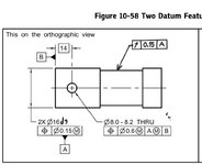
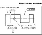
I don't really know why, but I am thinking that if the OD's (again fig 10-58, Ø16.51-16.56 outside diameters) are modified at MMC (hence being a clearance fit application--I know very simplistic way of thinking--) then if those two diameters are now datum features (call it "A") for the Ø8mm hole THEN the most logically this primary datum feature "A" should/ shall be modified at MMB. What would be the physical reality of an assembly to act as "clearance" fit in one place and then a "non-clearance" fir (press fit) in the other place on the same drawing for the same physical part?

Do you guys understand my question?
greenimi,
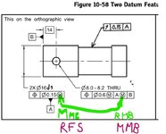
See below this modified version of the figure, where the position control of the two segments of datum feature A relative to each other is kept at MMC, the position tolerance for the 8 mm hole is kept at MMC and referencing datum A primary at MMB, and the newly added runout tolerance references datum A at RMB (as a side note, it would be possible to also add B secondary for the runout but it would be redundant in terms of the relevant degrees of freedom).

Do you find anything wrong with it or have any doubts about its usefulness?1000020888.jpg
 
Last edited:

Part and Inventory Search

Sponsor