Hi guys,
I'm trying to transfer 12VDC of power by means of using air core transfomer and my goal is to have regulated 9V at the end to power up a load circuit (arduino + leds + module). The schematic is attached. I read 1.3kHz on this setup.
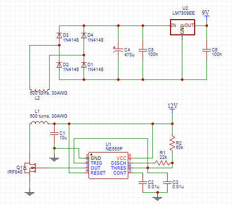
If I remove the load, the voltage across C4 can reach 20V, however if I put the load I only get around 4.0V.
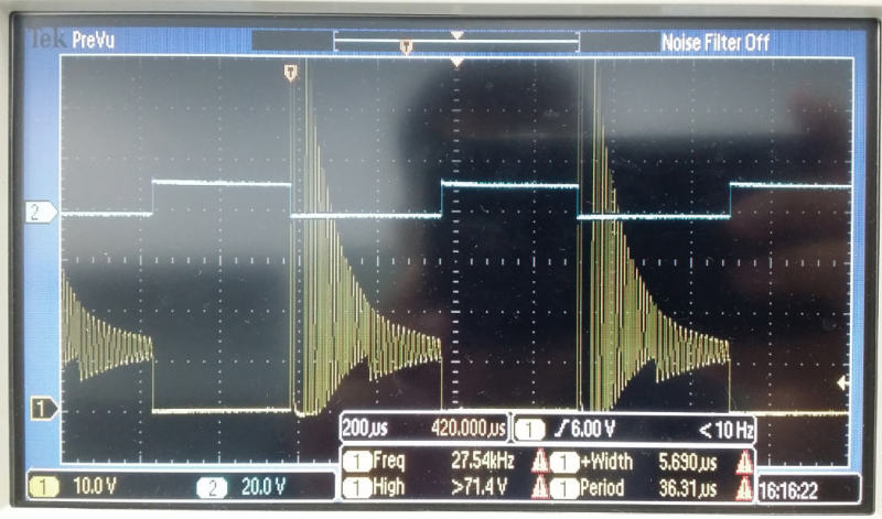
If I probe the FET Drain-Source it looks like the picture attached. I tried putting snubber across it in attempt to minimise the oscillation (values 2 Ohm, 2.2uF and around that) but it doesn't help.
So far I've tried:
1) Lowering or increasing the frequency by changing the values of R1,R2 and C3, but it couldn't increase the output.
2) Increasing the number of loops of both coils, but it doesn't help (tried 100 turns, 300 turns, 500 turns).
3) Rewinding primary coil on a slightly bigger diameter so that it gets nearer to the secondary. This increases the output by around 0.5V only. I can't make it bigger anymore because I need the primary to spin on a motor.
4) Changing the primary to 150 turns I can have 4.5V, however further reducing it didn't help to increase the output. It doesn't follow the rule N2/N1*Vin. Is this because of the inefficiency of without using core?
Limitations: I could only increase the input supply to max 15V and max 200mA for the NE555P to operate, based on its datasheet.
One question, if the coils are not evenly distributed, will that affect the result? I did the coil manually by hand.
Perhaps anybody can give some ideas of what went wrong or any alternative suggestions how to increase the voltage?
I'm trying to transfer 12VDC of power by means of using air core transfomer and my goal is to have regulated 9V at the end to power up a load circuit (arduino + leds + module). The schematic is attached. I read 1.3kHz on this setup.
If I remove the load, the voltage across C4 can reach 20V, however if I put the load I only get around 4.0V.
If I probe the FET Drain-Source it looks like the picture attached. I tried putting snubber across it in attempt to minimise the oscillation (values 2 Ohm, 2.2uF and around that) but it doesn't help.
So far I've tried:
1) Lowering or increasing the frequency by changing the values of R1,R2 and C3, but it couldn't increase the output.
2) Increasing the number of loops of both coils, but it doesn't help (tried 100 turns, 300 turns, 500 turns).
3) Rewinding primary coil on a slightly bigger diameter so that it gets nearer to the secondary. This increases the output by around 0.5V only. I can't make it bigger anymore because I need the primary to spin on a motor.
4) Changing the primary to 150 turns I can have 4.5V, however further reducing it didn't help to increase the output. It doesn't follow the rule N2/N1*Vin. Is this because of the inefficiency of without using core?
Limitations: I could only increase the input supply to max 15V and max 200mA for the NE555P to operate, based on its datasheet.
One question, if the coils are not evenly distributed, will that affect the result? I did the coil manually by hand.
Perhaps anybody can give some ideas of what went wrong or any alternative suggestions how to increase the voltage?
![URL]](https://res.cloudinary.com/engtips/image/fetch/w_800,c_lfill,q_auto,f_auto,g_faces:center/[URL unfurl="true"]http://hi-tecdesigns.com/images/pictures/Footwell%20Animation%20Tiny.gif[/URL])