Continue to Site

Eng-Tips is the largest engineering community on the Internet

Intelligent Work Forums for Engineering Professionals

  • Congratulations KootK on being selected by the Eng-Tips community for having the most helpful posts in the forums last week. Way to Go!

Hi there , I have an aeration syst 3

Status
Not open for further replies.

Sam1390

Chemical
Jul 10, 2018
18
Hi there ,
I have an aeration system that consists of a 6 meter tall aeration tank with approx. 5 m of liquid. The PD blowers are in a nearby building at ground level. The piping goes up and over the wall of the aeration tank to the bottom of the tank where the aeration diffusers are. I am going to calculate the height of the barometric loop for this system. can anyone help me how high it should go? Actually I don't even understand the reason of having a barometric loop here.
 
Replies continue below

Recommended for you

5m if you want the water to stay in the tank and pipe and not flood the blowers when the blowers are turned off. Or maybe you could install one or two check valves, if you want to keep it horizontal. Depends on how the pipe could enter the tank. Are the aerators part of the tank, or an independent fabrication?

--Einstein gave the same test to students every year. When asked why he would do something like that, "Because the answers had changed."
 
Thanks , actually the blowers is at the lower levels , I think that I should either put a vacuum break valve on the hump or lengthen the loop up to 1 bar + liquid level in the tank = 15 m
Am I right?
 
Sam1390,

A dimensioned and labelled sketch would go a long way here to prevent any possible misunderstandings.

Good Luck,
Latexman


The quick answer just write '' Barometric loop '' and search the web.. One of the outcomes (The barometric loop is a continuous section of the supply line that rises a minimum of 35' at sea level, above the highest point of the water used downstream, and returns back to the original level. The barometric loop works on the principle that a vacuum can only draw a head of water so far up a water column, and if the column is tall enough, a backsiphonage cannot draw the unwanted material back into the potable water.)

In your case , The raise ( and may jump ) of water in the pipe over the hump is , due to sudden pressure drop in the riser when the PD blower stops rather than siphon effect. The static water level in the riser (water side ) is 5.0 m . During operation of PD, water level in the tube is 5 m below at diffuser level . If the PD blower stops, causing damping oscillation of water in the riser.
I will suggest

- provide Check valve at hump or,
- prevent rapid pressure drop in the pipe with increasing the stopping time.

P.S . When all you have is a Hammer, everything looks like a Nail


Use it up, wear it out;
Make it do, or do without.

NEW ENGLAND MAXIM


There is no possibility of reverse flow into this pipe since it is entering the tank through the tank roof, from your description ( as you say ). Assuming this tank is operated at atmospheric pressure. But you will need to install some low point drip legs on this supply line to clear out condensate and keep the line from flooding up with condensate.
 
Thanks everyone for the responses. I got my answer and will out a check valve on top of the loop to break the siphonage.
 
A check valve will not break a syphon, only restrict reverse flow.
They often fail and cannot be relied upon to seal.

A diagram would still help.

Remember - More details = better answers
Also: If you get a response it's polite to respond to it.
 
Per LittleInch
A drawing of you plant piping is manditory for and meaningful discussion.
 
There is some risk that condensate drainers at low points may get bunged up with corrosion debris from this CS pipe. To be safer, use an on - off control valve to open and close on a DCS timer on each of these low points.
 
Do you have two tanks?

Remember - More details = better answers
Also: If you get a response it's polite to respond to it.
 

My vote is for VARIANT 1 . But add condense trap or at least drain tap at the lowest level , outlet of the blower .

Just saying.


Use it up, wear it out;
Make it do, or do without.

NEW ENGLAND MAXIM


Agree with LI that check valves are not considered to be reliable as they will leak.

You should have a valve with a failed close mechanism that will close either on power failure or shut off. This is done frequently in wastewater treatment.
 
I'm not sure what you're trying to do here and why.

When I said a NRV I thought you meant in the air line itself, but you mean a vacuum valve which I guess does act a bit like an NRV, but is a bit more sophisticated than that. However they can fail and then all your air just disappears out the vacuum valve.

If the concern is water leaking backwards down the pipe then a non return valve on the air line itself at the base of the tank would create a decent back pressure for it to seal against. Using two different ones in series would help the reliability. BIMRs suggestion is the best way for sure, but needs power and controls.

Or do that and add a vacuum relief valve at the high point. A 15m high loop or a high point 10m above water level seems rather OTT to me.

Or can you guarantee no negative pressure once the blowers turn off?

Remember - More details = better answers
Also: If you get a response it's polite to respond to it.
 
this is the basic design and there is a loop with a NRV as the siphon breaker . my understanding is we have two options : either having a barometric loop equal to water level + atmospheric pressure + margin or having a loop with water level height with a siphon or vacuum break valve.
the current design suggest a NRV but it is subject to confirm. I believe a NRV might be effective but if anyone has a better alternative, I am looking forward to hearing.
 
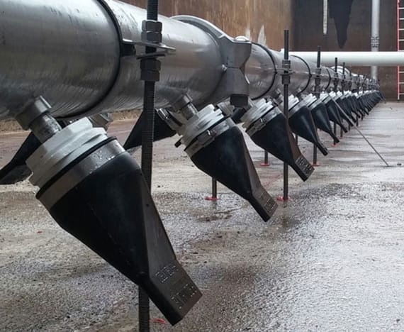
Replacing the nozzles on your aeration pipe with duckbills is an alternative to the vacuum breaker approach. Vacuum breakers and check valves do require regular maintenance if you do not plan on running to failure. In this case failure may damage your air pumps.

new-header-aeration-cropped_kxjhxg.jpg
Tideflex®
Disclaimer I use these duckbill valves in storm water applications, not aeration systems. In storm water they have long service lives.

I would still run the charging line above the rim of the tank wall. Loss of air pressure with these duckbill valves installed would at most result in a slow leak.
 
Status
Not open for further replies.

Part and Inventory Search

Sponsor