Continue to Site

Eng-Tips is the largest engineering community on the Internet

Intelligent Work Forums for Engineering Professionals

  • Congratulations GregLocock on being selected by the Eng-Tips community for having the most helpful posts in the forums last week. Way to Go!

High 2X axial vibration in uncoupled 2 pole sleeve bearing motor 5

Status
Not open for further replies.

edison123

Electrical
Oct 23, 2002
4,460
On testing an uncoupled, 2 pole (3000 RPM, 50 Hz) motor on sleeve bearings, I found the following axial vibration frequencies (mm/sec RMS) on DE bearing top cover.

Overall - 3.91 mm/sec RMS
0.04 at 1500 RPM
0.89 at 3000 RPM
3.00 at 6000 RPM
0.05 at 9000 RPM
0.07 at 12000 RPM

I confirmed it is not electrical vibration since the overall DE axial vibration did not drop immediately upon cutting off the motor supply. The motor test bed is a machined bed in which I have tested many high speed motors successfully, so no bed issues.

The overall axial vibration in NDE bearing top cover was only 1.5 mm/sec RMS. (I see normally axial vibrations on both bearings are almost the same).

Vibrations in DE & NDE Horizontal and Vertical were also less than 1.5 mm/sec RMS.

Any reasons why this high 2X axial vibration only in DE bearing ?

I am also posting this in mechanical forum to get their views, so don't RF me. :)

Muthu
 
Replies continue below

Recommended for you

is this a new motor? Refurbished ? Just being taken out of stores ? Were any repairs done to the shaft's DE bearing journal ?


I expect the the axial vibration measurement is being made on the DE bearing top cover close to the bearing, not out at the a larger diameter close to the windings.
What is the axial vibration on the equivalent location on the lower bearing cover ?

I'd do a simple "bump test" with a dead blow hammer etc, strikithe DE top cover axially close to the bearing, when the rotor has coasted down to 1000 rpm or so ( so the weight of the rotor is not yet directly connected to the end bell).

I think you will excite a 100 Hz/6000 cpm resonance of the DE bearing cover.

As to the mechanical condition exciting the resonance, I'd remove the top bearing cover and check the upper bearing insert for signs of rubbing. Then I would indicate the DE bearing journal at front. center, and rear. I expect you will find the journal has at least a few 0.001s inch TIR.
This runout may ("bent shaft") , or may not (half-fast shaft repair) extend to the DE shaft where a coupling etc will mount.
 
Tmoose said:
I'd do a simple "bump test" with a dead blow hammer etc, strikithe DE top cover axially close to the bearing, when the rotor has coasted down to 1000 rpm or so ( so the weight of the rotor is not yet directly connected to the end bell).
Yup, I have the same recommendation. It is pretty common for a large sleeve bearing motors to have a axial-direction resonance of the large thin plate at the ends of the motor above the bearings, similar to resonance of a drum.

Other ways of checking for that plate resonance:
[ul]
[li]map out the vibration, if the vibration is highest in middle of the plate and lower toward edges of plate, it matches resonance pattern.[/li]
[li]Also try pushing in the center of the plate and you may see a dramatic reduction in axial vibrations, it suggests resonance.[/li]
[/ul]

If you confirm plate resonance you may be able to solve it by stiffening the plate or arranging something to push in the middle of the plate. Or the gasket material and bolt torque may affect the resonance also (I have seen this type resonance appear and disappear after removing/reinstalling the cover).

The recommended TIR check is a good one too looking for potential sources of 2x on an uncoupled motor. I would say to also keep an open mind that it might possibly still be electrical twice line frequency exciting the vibration even though it persisted after deenergization (how long did the vib last after deenergization?). I think a lightly damped resonant system can take longer for vibration to die away after removal of exciting force than a non-resonant system.


=====================================
(2B)+(2B)' ?
 
Thanks guys. The motor was overhauled, rotor was rewound and the shaft journals and other shaft areas were grind polished with TIR of 0.1 0.01 mm max. Refurbished sleeve bearings supplied by the client were used. The DE bearing was opened up and no rubbing or skid marks were found in the white metal. Bearing seating on the bottom housing was also blue matched for over 90% seating.

I used two probes simultaneously on DE bearing top cover axial as shown below and both of them read the same values as above with 2x axial predominant. As can be seen, the top bearing cover is one solid unit with oil seals bolted at the front. The vibration was highest at the top (12 O' clock) and came down to 1.5 mm/sec at the bottom sump area. I too suspected resonance but did not have a solution to correct it given the top cover construction. The client was happy with 3 mm/sec vibration since it was running with 10 to 12 mm/sec before refurbishment, but I wasn't.

001_Vibration_probe_1_2_at_DE_Top_housing_wv1nnh.jpg


ETA: Soft foot was also checked and no change in axial (or any other) vibration was seen.

Muthu
 
A "wound rotor" motor (of the size shown in attached photo) can operate at 12,000 RPM?

The photo attached does not appear to be of a wound rotor type motor.
It looks like a traditional squirrel cage machine.

Differences in "nomenclature speak" have happened here before though.

The reason the drive-end 2X axial vibration is only at the DE bearing end... is because that end of the rotor
is not as precisely balanced as other portions of the machine. Or... (And I doubt this... but should be assessed...
or considered... the coupling and or key, is contributing to the less-than-better vibration readings.

One can bang on a machine, tip it up on one end etc. for better readings... but the end result is still the same.
A rotating element(s) that remains out-of-balance.

As noted though... the client is happy.

John
 
Hello John

It's a cage rotor at 3000 RPM where the rotor was 'rebarred' (aka rewound) and dynamically balanced with coupling to ISO G2.5 grade. The 12000 RPM is the vibration spectrum frequency, not the motor RPM.

The horizontal vibration was under 1.0 mm/sec and vertical vibrations was under 1.5 mm/sec on both sides. The coupling is 0.03 mm interference fit. So unbalance, loose fits, soft foot etc. were ruled out.

Muthu
 
Thank you for the clarifications related to the motor's actual rotor construction and RPM spectrum freq.

I've raised the "beef" here in the past related to motor part names or nomenclature.

An Armature is not the same as a Wound Rotor.
Slip rings are not commutator bars.

Those reading on... get the point.

Granted; terms, descriptions and names differ from one part of the world to another.

At least we seldom read, "... the electric engine was powered by a dynamo."

Enjoying the board,

John
 
As can be seen, the top bearing cover is one solid unit with oil seals bolted at the front.
I'm not sure whether or not you're drawing any conclusion from that description / photo. But for me it doesn't rule out the vibrating flimsy end plate scenario at all. The resonant flimsy plate moves the solid bearing housing. That may not seem intuitive, but I have seen the proof... for example I have seen where you can go up and push your hand into the middle of the flimsy plate and watch the vibration go down on the vib meter monitoring the solid bearing housing below. Also the axial vibration higher at 12:00 than 6:00 fits this scenario.

I just posted the above to avoid misunderstandings (I wasn't sure why you highlighted the stiffness of the location of the vibration mount and never reported any vib readings on the plate itself). But I think you are probably looking at it the same way based on your other comment:
I too suspected resonance but did not have a solution to correct it given the top cover construction. The client was happy with 3 mm/sec vibration since it was running with 10 to 12 mm/sec before refurbishment, but I wasn't.


=====================================
(2B)+(2B)' ?
 
pete

I don't know what you mean by a flimsy plate, this is a whole unit of cast iron housing. The high axial readings I posted are at this location.

Muthu
 
I was referring to the semi-circular plate above the bearing housing (not where you're monitoring). If yours is cast, my scenario might not be as likely but the checks I suggested are very easy (vibration check on the plate, examine effects of pushing on the plate or stiffening the plate).

=====================================
(2B)+(2B)' ?
 
Sorry for belaboring this point. It may or may not be the case for your machine, but just for info here is a thread where I documented a case like I've been talking about
In case you can't retrieve the attachment from that site, I have attached it here.

Edit - I'll add a summary from the other thread here:

electricpete case summary said:
This is a 7,000hp 3,600rpm 13.2kv horizontal tilt-pad radial bearing motor…

Slides 1 through 10 are waterfall drawings, but slide 1 is the only one of interest (all the others show no change). The outboard bearing axial (1A) 1x vib jumped from 0.13 ips to approx 0.4 ips (above the scale of the waterfall) between Nov 2010 reading and November 2011. In between these times the only thing we had done was
1 – We removed/reinstalled endcovers for inspection.
2 – We re-aligned the machine.

Slide 11 = Overview of the motor outboard end.
Slide 12 = closer view, labeled with vibration measurements. While the bearing cap reads 0.4 ips, the center of the upper endshield reads approx 1.2 ips. By pressing on the center of the upper endshield, you can make the bearing vibration go down.

Slide 13 = First vibration reducing device. Simply placing this loosely inside the two endshield handles cause bearing axial vibration to decrease to 0.25 ips….

Slide 14 = 2nd vibration reducing device. Placing this heavy bar tightly inside the two endshield handles (it was a tight fit... had to hammer it in) caused bearing axial vib to decrease to approx 0.25 ips. Clamping the device to the outside of the handles caused bearing vib to decrease to 0.19 to 0.2 ips. It appears adding mass is more effective than our stiffening attempts.


=====================================
(2B)+(2B)' ?
 
Hi edison123,

I'd take a waterfall of spectra letting the motor coast down. I'd be interested what the 2X spike does when the rotor has slowed to ≈ 2700, 2400 and 2100 rpm.

" the shaft journals .........were grind polished with TIR of 0.1 mm max."
hmmm. so .004 " TIR with opposite "high" spots at each end of the DE bearing journal are not completely out of the question.

3 MM rms at 6000 cpm is about .0005" pk to peak.
For the coast down I would also position a dial indicator measuring axially on the end bell "hot spot" , and mounted to ground and watch the reading real time.
At some rpm the indicator will be able to track the motion. Maybe 1000 rpm or less.
If the indicator shows the end bell is being driven mechanically to "pant" axially 0.0005" TIR at low speeds, it won't take resonance to do the same thing at speed.
 
Tmoose - you come up with some interesting well thought out checks, and I always study them to try understanding them and learning from them.
If the indicator shows the end bell is being driven mechanically to "pant" axially 0.0005" TIR at low speeds...
I assume by "TIR" you really meant peak to peak, right? (the term TIR doesn't make sense to me in this context where I thought neither the tip nor base of the indicator is rotating)

How did you come up with 0.0005" as an acceptance criteria? Does it have some relation to the other numbers, or maybe just a minimum peak to peak displacement that can be reliably detected?

Could this also be done while rotating the shaft by hand (instead of coastdown)?

deleted question: In the case that I posted, the "hotspot" would have been the center of the upper endshield where we has 1.2 ips (slide 12)? I'm not sure what would be the logic of selecting the peak of the resonant modeshape for testing at a non-resonant (lower) frequency.


=====================================
(2B)+(2B)' ?
 
pete - Now I get what you meant by flimsy plate. Yes, that is the top 'end shield cover' that is fitted after the bearing top is fixed. It is indeed a flimsy cover like the one in your PPT. I did not check to see if putting pressure on this plate affected the bearing top cover vibration. I will definitely ask the client to check at his end when he does the decoupled run at his site next week. Thanks for the tip with a real life example.

Tmoose - The TIR was 0.01 mm, not 0.1 mm, sorry about the typo, which I have corrected now. Thanks for catching it. I used a DC motor driven AC generator to start this motor from zero speed to full speed at 3.3 KV over a 2 minute ramp (good ole electrical VFD). During coasting up, I watched axial vibration at the bearing top cover and saw it laying low until around 2900 RPM and then hit the peak at 3000 RPM. The coasting down took 28 minutes but I did not record the vibration during this period.

Muthu
 
Hi pete

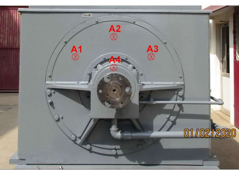
Just to be clear, in the photo below, if you apply axial pressure at points A1, A2 & A3 in the top cover plate, you expect the axial vibration at A4 (at DE bearing top cover) to change if there is a top plate resonance?

BFP_2A_Axial_photo_uk2b8x.jpg


Muthu
 
Just to be clear, in the photo below, if you apply axial pressure at points A1, A2 & A3 in the top cover plate, you expect the axial vibration at A4 (at DE bearing top cover) to change if there is a top plate resonance?
Yes, that's what I expect if there is a top plate resonance. Most likely the biggest effect when applying pressure at A2. I also expect vibration at least twice as high at A2 compared to A4.

=====================================
(2B)+(2B)' ?
 
Hi EPete,

"How did you come up with 0.0005" as an acceptance criteria? Does it have some relation to the other numbers, or maybe just a minimum peak to peak displacement that can be reliably detected?"

3 mm/sec rms is about .5 mils or 0.000,5 inch pk-pk according to this -

I should have mentioned I'd be expecting two "high spots" per shaft rotation.

If something about the bearing is cranking, or being cranked, mechanically to move ±.00025" (.0005" Total Indicator Reading [bigsmile] ) axially 2X at some low speed, it is little wonder it is probably going to do the same thing at higher speeds. Naturally resonance can make it do the wild thing at some higher speed. The relationship of constant motion/ Mils "vibration" to velocity or acceleration at varying speeds can and WILL hide some basic mechanical shenanigans that rotating machinery is so fond of.

When I was lugging a data collector/analyzer around New England every day for several years >>several years back, I also had my own personal 1" travel indicator with any-form mag base in my kit. That indicator helped answer a LOT of "vibration" questions.
 
Hi edison123

"I watched axial vibration at the bearing top cover and saw it laying low until around 2900 RPM and then hit the peak at 3000 RPM."

Was that just the overall reading, or were you able to track the 2X vibration also?
 
Hi Epete,

"Could this also be done while rotating the shaft by hand (instead of coastdown)?"

Possibly, but the shaft would have to be up on the hydrodynamic oil film pretty good, and I would have to promise not to apply anything but a rotating moment to the shaft.
Also the axial wiping or lifting motions and forces I am dreaming about might need to be left alone to react against the rotor mass and shake or tip the bearing housing on that cantilevered mount.

OH !OH ! I just thought of something else.

I'd measure the vertical and horizontal vibration on the DE bearing at speed. Front, center and rear. Please see the attached image . Spectra at least. 2X amplitude and phase if possible
 
 https://files.engineering.com/getfile.aspx?folder=2c57f529-c2ec-41bb-8917-5d21f0ec5558&file=001_Vibration_probe_1_2_at_DE_Top_housing_-annot.jpg
Status
Not open for further replies.

Part and Inventory Search

Sponsor