Navigation
Install the app
How to install the app on iOS
Follow along with the video below to see how to install our site as a web app on your home screen.
Note: This feature may not be available in some browsers.
More options
Style variation
-
Congratulations TugboatEng on being selected by the Eng-Tips community for having the most helpful posts in the forums last week. Way to Go!
You are using an out of date browser. It may not display this or other websites correctly.
You should upgrade or use an alternative browser.
You should upgrade or use an alternative browser.
High density between contact 1
- Thread starter Miss Mimi
- Start date
- Status
- Not open for further replies.
-
1
- #2
- Thread starter
- #3
Hi FEA way,
I am very sorry for late reply.
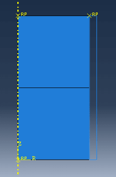
Actually I want to model a compaction of bilayer iron powder. Iron powder itself I model it using solid, deformable bodies as per attached (Figure 1) with 0.5 Quad-mesh.
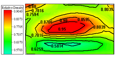
But I did not get as I done on my experimental image (result of final compaction of bilayer). I found that highest density happened at the interface located at the line between upper and lower layer of powder (as in Figure 2).
Therefore, I currently use ABAQUS/Explicit. May I know how to get the red effect at the middle region between upper and lower layer of modeling?
Thank you
Maybe it’s because I’m reading this on my phone but I can’t see the second image with results (only Figure 1). Are you sure it’s attached ?
Also please give more details about the analysis setup (especially boundary conditions and loads but also material models and such). With this information it will be much easier to help you achieve expected result.
Also please give more details about the analysis setup (especially boundary conditions and loads but also material models and such). With this information it will be much easier to help you achieve expected result.
- Thread starter
- #5
Good day FEA way,
Currently, i am modeling an axisymmetric bilayer compaction which consists of 5 parts:
die, lower layer of powder, upper layer of powder, upper punch and lower punch.

Part Module - Both upper and lower layers are same in dimension. where the diameter is 10mm, and height is 10 mm. (as referring in Figure 1)
Property Module - I am applying elastic and Cap Plasticity (with the use of USDFLD subroutine)
Assembly Module - Model are assembled as in Figure 1 in axisymmetric form
Step Module - There are total of six steps all together so that, the steps can be similar as done in compaction experiment. The
first layer is compact first, and the upper punch raise and consequently, compact the upper layer, thus finally
form a solid bilayer tablet
Interaction module - all simulated as surface-based interaction.
Between bottom punch and lower layer is defined under surface-to-surface interaction
Between die wall and right side of lower layer is defined under surface-to-surface interaction
Between die wall and right side of upper layer is defined under surface-to-surface interaction
Between upper punch and top side of upper layer is defined under surface-to-surface interaction
Between upper punch and top side of lower layer is defined under surface-to-surface interaction
For modeling the interface between two layers (between top side of lower layer and bottom side of upper layer) is
defined under surface-to-surface interaction. All of the above mentioned interaction have applying penalty of friction
coefficient of 0.3
.....in order to get effect of higher density as obtained in experimental image of Figure 2.

Load Module - So far, i am using the punch displacement (Boundary Condition) to deform these two layers of deformable bodies.
Mesh Module - Mesh is in Quad-shape with size of 0.5 for both layers
However, in my case, i did not get the red effect as similar in my experiment.
Thank you FEA way for your kind help.
Currently, i am modeling an axisymmetric bilayer compaction which consists of 5 parts:
die, lower layer of powder, upper layer of powder, upper punch and lower punch.

Part Module - Both upper and lower layers are same in dimension. where the diameter is 10mm, and height is 10 mm. (as referring in Figure 1)
Property Module - I am applying elastic and Cap Plasticity (with the use of USDFLD subroutine)
Assembly Module - Model are assembled as in Figure 1 in axisymmetric form
Step Module - There are total of six steps all together so that, the steps can be similar as done in compaction experiment. The
first layer is compact first, and the upper punch raise and consequently, compact the upper layer, thus finally
form a solid bilayer tablet
Interaction module - all simulated as surface-based interaction.
Between bottom punch and lower layer is defined under surface-to-surface interaction
Between die wall and right side of lower layer is defined under surface-to-surface interaction
Between die wall and right side of upper layer is defined under surface-to-surface interaction
Between upper punch and top side of upper layer is defined under surface-to-surface interaction
Between upper punch and top side of lower layer is defined under surface-to-surface interaction
For modeling the interface between two layers (between top side of lower layer and bottom side of upper layer) is
defined under surface-to-surface interaction. All of the above mentioned interaction have applying penalty of friction
coefficient of 0.3
.....in order to get effect of higher density as obtained in experimental image of Figure 2.

Load Module - So far, i am using the punch displacement (Boundary Condition) to deform these two layers of deformable bodies.
Mesh Module - Mesh is in Quad-shape with size of 0.5 for both layers
However, in my case, i did not get the red effect as similar in my experiment.
Thank you FEA way for your kind help.
Ok, now the goal and setup of the analysis is clear. However to determine what causes the difference between results from experiment and those from simulation I would have to take a look at the relative density plot that you generated from the analysis. Boundary conditions seem valid. However you should make sure that material model is correct. Especially that it is implemented via user subroutine. Also check contact properties. Especially friction behavior may play important role in this case. Maybe it should be adjusted to match experiment.
Do you use some particular scientific article as a reference ?
Do you use some particular scientific article as a reference ?
- Thread starter
- #7
Good day FEA way, ![[bigsmile] [bigsmile] [bigsmile]](/data/assets/smilies/bigsmile.gif)
So far, i did not have any plotting graph of relative density between experimental and modeling. I am just compare based on the image that i had been obtained.
I am always refer to a thesis written by Hossein Kashani Zadeh (2010) for material properties of iron. The iron powder has its own formulation (Brewin equation) to generate its material property (elastic and Cap Plasticity) along its increasing relative density between range of 0.5 to 1.0 (or 3.5 g/cm^3 to 7.0 g/cm^3) during compaction.
However, no any paper that build the bilayer compaction model based on Finite element (FE) but they always used particle method.
The attach given is the thesis by Zadeh
Actually, i am stuck on this modeling for long time and i do not have reference, FEA way thank you for your kind feedback
![[bigsmile] [bigsmile] [bigsmile]](/data/assets/smilies/bigsmile.gif)
So far, i did not have any plotting graph of relative density between experimental and modeling. I am just compare based on the image that i had been obtained.
I am always refer to a thesis written by Hossein Kashani Zadeh (2010) for material properties of iron. The iron powder has its own formulation (Brewin equation) to generate its material property (elastic and Cap Plasticity) along its increasing relative density between range of 0.5 to 1.0 (or 3.5 g/cm^3 to 7.0 g/cm^3) during compaction.
However, no any paper that build the bilayer compaction model based on Finite element (FE) but they always used particle method.
The attach given is the thesis by Zadeh
Actually, i am stuck on this modeling for long time and i do not have reference, FEA way thank you for your kind feedback
- Thread starter
- #8
Good day FEA way,
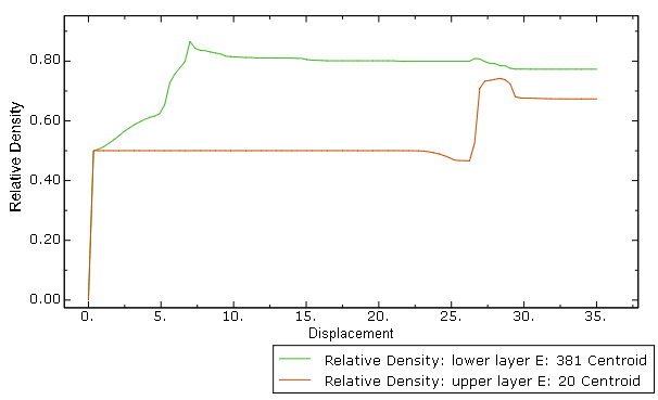
This is a graph from ABAQUS/Explicit analysis of relative density plot from upper and lower layers against displacement.

We can observe that the lower layer is more dense compare to upper layer of bilayer tablet at the end of compaction stage.
In my case, the plot of relative density from experimental compaction can only be done in form of contour.
This is a graph from ABAQUS/Explicit analysis of relative density plot from upper and lower layers against displacement.

We can observe that the lower layer is more dense compare to upper layer of bilayer tablet at the end of compaction stage.
In my case, the plot of relative density from experimental compaction can only be done in form of contour.
- Status
- Not open for further replies.
Similar threads
- Replies
- 2
- Views
- 11K
- Replies
- 5
- Views
- 16K
- Locked
- Question
- Replies
- 2
- Views
- 2K
- Replies
- 7
- Views
- 13K
