Eng-Tips is the largest engineering community on the Internet

Intelligent Work Forums for Engineering Professionals

High Pressure separator Level Control Valve position U/s or D/s a HeatExchanger / Heater in a GOSP

Status
Not open for further replies.
Dec 28, 2020
19
0
0
US
Rafa_schemes_abpvtw.jpg
Hello,
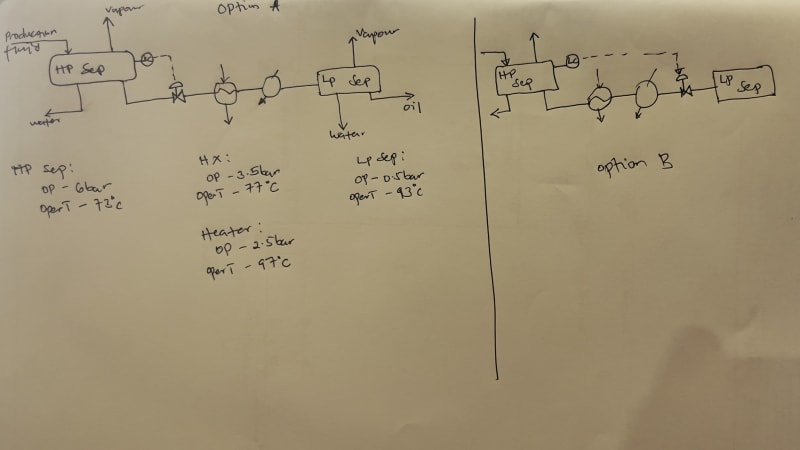
I currently have two design proposals I am assessing related to level control of a high-pressure separator. To give context, the oil stream from the separator passes through a heat exchanger (shell and tube) then a crude oil heater to the low pressure separator. Whilst assessing the two scenarios the following is what I could make of the considerations:

Option A of the high pressure separator's level control considers placing the LV upstream the heat exchanger basing on the need for fast response to control the separator level. The assumption made by A is that placing LV downstream the exchanger introduces an additional lag in response as a result of the exchanger and heater units.

Option B on the other hand considers placing the valve downstream the crude oil heater basing on potential for vapor flash if placed upstream and a need to avoid pressure drop to ensure liquid is handled in the exchanger sets and heater. Additionally, there is potential for exchanger thermal shock if the LV, when placed upstream fails which has potential to affect performance.

Given that both options have pros and cons, I am enquiring on your technical expert opinion on the matter.

Thx
Sesq
 
Replies continue below

Recommended for you

Unless there are valves to haven't shown the HXs will be iterating at the pressure of your LP separator plus a little bit for frictional losses.

As the liquid will be at bubble point in the HP separator as soon as it goes past the CV it will gas off and become about 50 liquid /gas.

The HX won't like that....

Option B keeps it all liquid so response time will be instantaneous. Don't know why you think it wouldn't be? You're controlling on level not temperature.

Option B all the way. IMHO.

Remember - More details = better answers
Also: If you get a response it's polite to respond to it.
 
take into account that you deal with a saturated fluid at all points of hydraulic path. This is a critical point for text below.

Option B will not work. The reason is control valve's rangeability. You have a very large operation range of CV at option A caused by fluid's cavitation or even flashing in CV's seat. At option B vapor fraction will be much greater and therefore greater Cv range required.

This cavitation at option A makes proper controlling at design range is hard or even impossible. This fact causes the problem that you might need 2 CVs in parallels with control range split.

image.png


Also important point is that option B requires total liquid CV inlet conditions as 2-phase CV exist/work only in theory. This in turn requires that a fluid pressure shall be higher that vapor pressure plus some margin at every point between HP separator and CV. This will require high elevation difference between HP separator and CV. This in turn will decrease dP available for HEs intensification.

No magic, the core idea is simple. All you need is to calculate and compare Cv at min, norm and max cases during options A and B and you will see I am trying to tell.

Note:
- real (not declared) rangeability of most industrial CVs is only 8; cage and ball CVs have a potential to provide 10 and 15 respectively with some cost and durability penalties
- 2 CVs in parallels design overcomplicates design of downstream overpressure protection
- both options seems risky from point of auto control of loop; there are some doubts that control system will be able to control loop in auto mode because of cavitation/flashing
- hydraulic study is critical for cases such kind of, make sure that hydraulic is calculated correctly and precisely for all operation cases possible
- such design is crotchety; a minor change/intervention/deterioration affecting hydraulic during operation stage will make worthless all CV modelling done during design stage

PS
It is impossible water will decant at LP separator as liquid has been heated upstream. Doublecheck saturation calculations.
 
shvet,

I will have to disagreee with you and your post doesn't seem to make a lot of sense as you say both options won't work.

Also " 2-phase CV exist/work only in theory. " Really? I wonder how hundreds of thousands of choke valves work then?

Or any CV downstream of a separator?

You need to be open with the CV vendor about the physical properties, but this situation ( basically flashing a liquid into liquid and gas, happens many times in a process plant with a single valve.

Also why would water not "decant" - I assume you mean separate out from the condensate. Temperature is a little high, but I see no reason why it wouldn't.

you are probably right to point out that the additional heat will create two phase flow unless the HX as a long way below the separator, but it's still a lot less in option A than it is in option B and HXs tend to work better with single phase liquid.

In fact heating the incoming fluid might be a better option all round.

Remember - More details = better answers
Also: If you get a response it's polite to respond to it.
 
@LittleInch

Let me reply step by step. Let me point out that core idea is simple and quite obvious to everyone involved in detailed process design before. Real operation rangea is the only question.

you say both options won't work.
No. A is risky from auto control mode. B will not work.

Also " 2-phase CV exist/work only in theory. " Really?
I meant 2-phase inlet and outlet conditions both simultaneously.

I wonder how hundreds of thousands of choke valves work then?
1/ I have dealt with many CVs having 2-phase outlet conditions. I have not heard about CVs having 2-phases inlet and outlet both.
2/ What do you mean "choke" valve? Flashing?

Or any CV downstream of a separator?
Did not understand. Explain please.

You need to be open with the CV vendor
I have a negative experience with CV vendors cooperation as those are prone to consider itself not responsible for process design and reliability of Cv calculation input data.

situation ( basically flashing a liquid into liquid and gas, happens many times in a process plant with a single valve.
Correct. But what flashing rate? V/L fraction = 1:1 or 10:1 or 1000:1 or 1000000:1? One case is when you deal with V:L 1:10 outlet condition in range from min 1:20 to max 1:5. Completely different case is when you have to control in range from 10:1 to 1000:1. And what about you calculations accuracy? What if fluid properties will slightly change? What if CV will have some Cv inaccuracy caused by manufacturing technology or test procedure? An so on and on. So many things critically affecting actual flashing.
And the only way to compensate these uncertainties/inconsistencies is a operating personnel which will have to adjust actual hydraulic manually.

Design should be cheap+robust+proven+simple. "Quadratisch. Praktisch. Gut"(c). Is such design able to be called sound, robust, or inherently safe? What do you think?

Also why would water not "decant" - I assume you mean separate out from the condensate. Temperature is a little high, but I see no reason why it wouldn't.
Yes, decant means water phase. I am used to in projects I have been involved in L-L separators are called decanters.
Water-oil coming out from HP is in equilibrium. After this fluid is heated and L-L equilibrium moves to undersaturation. After this fluid is flashing and light hydrocarbons and part of water got removed. Why L-L equilibrium shall move to saturation? Temperature change? No, liquid stays overheated 20°C. L-L solubility change? No, solubility changing is negligible.

Can you explain the logic of 3rd phase LP separator?

but it's still a lot less in option A than it is in option B and HXs tend to work better with single phase liquid.
To work with total liquid phase vapor pressure shall be considered. This might require an extremely high elevation with subsequent cost penalty.

PS
For option B main point is actual operation range. If operation range is let's say 1:1.2 then CV in theory is able to work properly. If operation range is 1:2 or higher then 2 CVs in parallels is required or more likely in reality it will not work at all or will not work after some time in operation.
Option A is more sound and predictable.
Anyway any design mistakes are able to be compensated by operating personnel. Unfortunately I am encountering such situation regularly.
 
Option B is preferred on the condition that a booster pump is installed upstream of the 2 heaters to keep the fluid as single phase liquid, else 2 phase (liquid - vapor) splitting at either or both of these 2 heaters is going to result in thermal duty failure.
 
Not easy putting a pump in that fluid at saturation pressure. You would need a vertical drop of several metres to the pump inlet.

Better to heat up the incoming fluid I think.

Shvet,

Choke valves sit on the top of oil and gas wells to control three phase flow in and out.

Separators are a bit notorious for being designed for one set of flow rates and composition but used for lots of other ones...

I still think option B is the last worst option here.

To be fair though at least Option A you know you're dealing in two phase flow so you can design your heat exchangers accordingly.


Remember - More details = better answers
Also: If you get a response it's polite to respond to it.
 
Guys, come on..

For this scenario, Option A is the most common. All my 3 FPSO's have this configuration for the first separator going into the second. No problem whatsoever, just design the entire system (valve, HEX) accordingly.

We often put the level control kinda like option B when we are feeding an electrostatic separator to ensure it will operate with no gas phase. In that scenario, the level control valve for the stabilizer vessel/2nd stage separator will be downstream of the electrostatic separator (and often even downstream of coolers and fiscal flow meters).


Best regards,

Daniel
Process Engineer
Rio de Janeiro - Brazil
 
We only have a little sketch so don't know anything about the HXs, but they will need to be bigger to cope with all the gas, but are a little strange - really not sure why there are there.

So we don't know if Option B will keep the liquid errr liquid or whether it creates gas inside the HX.

Details make a difference here.

Remember - More details = better answers
Also: If you get a response it's polite to respond to it.
 
In the case that the fluid flashes passing through the valve, the Option B is the best.
The scenario is similar to the cascade heater drain system of the power plants, where saturated water passes from a condensate heater to other with less pressure through a drain pipe with a level control valve.
The saturated water flashes when passing through the control valve that usually is installed at the end of the pipe near the second heater inlet. The pipe size after the control valve has more size that the pipe before because the flashed water has more specific volume ad so provoke more pressure drop. The reason is to optimize the pipe size.
 
The HEX are heaters, so the fluid will open a vapor phase nevertheless and now the valve has to handle two phase flow anyway.

Daniel
Process Engineer
Rio de Janeiro - Brazil
 
Heat exchangers in this fouling application will probably also require
a) Generous fouling factor on the crude side
b) Provisions for crude side cleaning
c) Antiscale chemical injection upstream of the heat exchangers
d) Some flow surge factor adder to the design case duty
Also, in the event the tube bundle is all carbon steel, make provisions to remove tube bundle in the future for new bundle when tube breaks become un manageable
 
The OP seems to have vanished, but that S+T HX doesn't seem to doing very much.

The Crude heater can probably be made fairly robust to handle two phase flow.

Remember - More details = better answers
Also: If you get a response it's polite to respond to it.
 
The first HX is most likely a heat recovery step using the heat from the hot dehydrated crude from the LP sep; it probably saves a fair bit on hot oil utility demand at the 2nd HX. If there were to be just a single HX in this scheme, there wouldnt be a need for this pressure boosting. Something to weigh up for decision making.
 
Let me sum written above. Let me remind that topicstarter has posted this issue in the forum entitled "Chemical engineers / Chemical plant design" while dedicated forum groups exist for energy and oil&gas industries issues.

One has no reasons to believe that this equipment will be installed in upstream (@LittleInch) or energy industry (@casflo). One does not know what oil is heated, it may become even used cooking oil or palm oil. What reason all of you think you know the case? Topicstarter vanished long time ago and are not participating in discussion. We are discussing a hypothetical oil in hypothetical HEs in hypothetical unit in hypothetical industry. Why is everyone of us discussing his/her private case he/she is most familiar with?

This topic looks like a talk of a blind with a deaf.

Option A

Pros

1/ Pressure driven heat train
total dP available ~5 bar => high max dP available => high velocities => high Reynolds => high heat transfer efficiency + low fouling => low weight and cost + high time in operation

2/ Mean dT
heat train operates with boiling => liquid latent heat + volume expansion => high mean dT + high Reynolds => see /1/

3/ Elevation
heat train and LP separator are able to located above HP separator => no elevation required other that drain and total liquid CV inlet provisions => equipment is able to be located on ground => low cost + higher safety

4/ Pressure
heat train operates with low pressure => less probability of release => higher safety

5/ Design margins
Operating ranges are more simple and predictable. I do not know how to describe this briefly.

6/ Auto control
narrow volumetric rate range => narrow Cv range required => more simple and reliable CV + no human-factor => low cost + robust design + higher safety

7/ Experience
I have checked 9 Basic Design Packages of hydrotreating and hydrocracking units I have been involved in the past engineered by different Licensors having such design (separator, CV, heat train). All 9 units have been designed as per option A. And I see no reasons those should have been guided otherwise.

Cons

1/ 2-phase
risk of unstable regime of flow => risk of flow-induced vibration in HE and piping

Option B

Pros
Can anyone argue what pros does Option B have? I have found only 3 arguments above:
- "The HX won't like that...." @LittleInch - what does it mean? I did understand
- "thermal duty failure" @georgeverghese - what logic does this failure occur? I did not understand
- "The scenario is similar to the cascade heater drain system of the power plants" @casflo - why a case from power industry (clean water) should be implemented in process industry (dirty oil)? I did not understand

I see no pros other than vibration. Is vibration so dangerous and uncontrolled? Is vibration not be able to be compensated by design? As for me such boiling oil is typical situation in process industry

Cons
Vice versa as option A.

Can anyone provide arguments why Option B should be preferred? Not kind of "I have a bad feeling about this" or "I saw such in the past" as experience is not relevant in the hypothetical case.
 
Shvet,

The post calls this a "High pressure separator... in a GOSP"

GOSP - Gas Oil Separation Plant - is a very common term for a facility in the upstream oil and gas world
The OP diagram enters with "production fluid" - very common description of fluids froma production well, oil or gas field/
There are multiple references to "Crude Oil" and "oil stream"
The whole set up is very common for initial high pressure separation of gas, liquid Crude oil or condensate and free water to remove much of the water and gas followed by a further lower pressure separation / flashoff of the liquid to create a more stabilised fluid for transportation and further processing.

IME this is >95% an upstream oil and gas system.

We know very litte about the design but what we do know is unclear.
My preference for Option B is that whilst there may be some flashing of the fluid after heating it, the fluid will or should remain more like 90% liquid which makes it a lot easier to heat compared to the lower pressure flashed off fluid in option A where it could easily be 50% liquid and 50% gas.

Yes there are other issues such as DP and lower pressure is usually better, but 6 bar to 3 bar isn't a lot.

Both have issues which can be resolved by correct design of the HXs and valves.

Remember - More details = better answers
Also: If you get a response it's polite to respond to it.
 
LittleInch said:
The post calls this a "High pressure separator... in a GOSP"

GOSP - Gas Oil Separation Plant - is a very common term for a facility in the upstream oil and gas world
The OP diagram enters with "production fluid" - very common description of fluids froma production well, oil or gas field/
There are multiple references to "Crude Oil" and "oil stream"
The whole set up is very common for initial high pressure separation of gas, liquid Crude oil or condensate and free water to remove much of the water and gas followed by a further lower pressure separation / flashoff of the liquid to create a more stabilised fluid for transportation and further processing.

IME this is >95% an upstream oil and gas system.
Thank you
 
Shvet, I agree that there are not enough data to fully analyze the question. The fluid vapor pressure, the height between both separators, the C. V. pressure drop ,etc. are unknown. But in relation with the possible flashing of the oil stream, other aspect to take into account, is the influence in the opening position of the C. V.
It seems clear that the length of pipe and equipment with flashing may be greater in the Option A than in the B and therefore to compensate the greater pressure drop, the C. V. must function more open in the Option A with less control capacity.
 
Status
Not open for further replies.
Back
Top