Continue to Site

Eng-Tips is the largest engineering community on the Internet

Intelligent Work Forums for Engineering Professionals

  • Congratulations KootK on being selected by the Eng-Tips community for having the most helpful posts in the forums last week. Way to Go!

High Pressure separator Level Control Valve position U/s or D/s a HeatExchanger / Heater in a GOSP

Status
Not open for further replies.
Dec 28, 2020
19
Rafa_schemes_abpvtw.jpg
Hello,
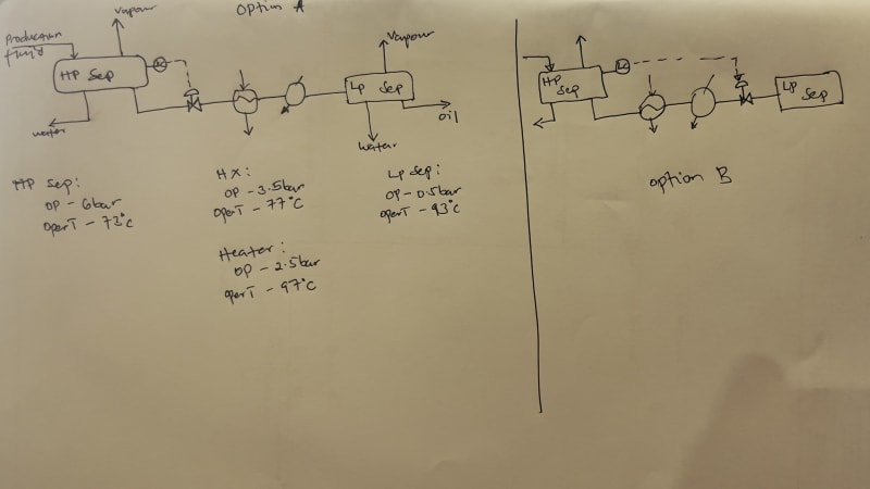
I currently have two design proposals I am assessing related to level control of a high-pressure separator. To give context, the oil stream from the separator passes through a heat exchanger (shell and tube) then a crude oil heater to the low pressure separator. Whilst assessing the two scenarios the following is what I could make of the considerations:

Option A of the high pressure separator's level control considers placing the LV upstream the heat exchanger basing on the need for fast response to control the separator level. The assumption made by A is that placing LV downstream the exchanger introduces an additional lag in response as a result of the exchanger and heater units.

Option B on the other hand considers placing the valve downstream the crude oil heater basing on potential for vapor flash if placed upstream and a need to avoid pressure drop to ensure liquid is handled in the exchanger sets and heater. Additionally, there is potential for exchanger thermal shock if the LV, when placed upstream fails which has potential to affect performance.

Given that both options have pros and cons, I am enquiring on your technical expert opinion on the matter.

Thx
Sesq
 
Replies continue below

Recommended for you

LittleInch said:
fluid will or should remain more like 90% liquid which makes it a lot easier to heat compared to the lower pressure flashed off fluid in option A where it could easily be 50% liquid and 50% gas.
...
6 bar to 3 bar isn't a lot.
1/ Do you mean mass of volumetric V/L ratio?

2/ "which makes it a lot easier to heat" - how does it actually work? I do not understand. Point postulated has no sense from theory point of view.
(a) More flashing => more vapor fraction => more latent heat involved => less temperature rise => more mean dT => more overall heat transfer efficiency
(b) Boiling has ~100 times higher heat transfer coefficient thaт liquid has => the more boiling the higher efficiency.

4/ 6 bar to 3 bar is 100% (2 times) more. Is 100% not a lot? 2 times? 2 times less leaking rate? 2 times less metal stress? 2 times less vapor expansion and density? Sounds like 0.1 bara and 0.5 bara difference is not a lot as this is only 0.4 bar.
5/ You recommend to route a 2-phase fluid having 0.1 vapor fraction to CV, correct?

casflo said:
length of pipe and equipment with flashing may be greater in the Option A than in the B and therefore to compensate the greater pressure drop, the C. V. must function more open
How is length related to CV open? We are discussing a new installation with a new CV. Why is CV not able to be designed correctly? Why does CV need correction? Why is excessive length not able to be compensated by pipe diameter or CV's Cv? Why has Option A to have more length than Option B?

Seems meaningless to me.
 
Shvet, I´ll try to clarify your doubts.
My previous comments assume that the topicstarter has a single C. V. that wants to know what is the best option to install it.
From the data of the Option A, assume to simplify that the pressure drop in the pipe from the H. P. Separator to the HX outlet is 0 and that the total pressure drop of 6 - 3.5 = 2.5 bar corresponds 2 bar to the C. V. and 0.5 bar to HX for the unknown design flow rate W.
If for example, the oil vapor pressure with T = 77ºC is Pv = 3.5 bar, this means that the flashing begins at the HX outlet and from here to the L.P. Separator, the pipe and the heater has flashing.
Now, turn to the Option B. For the same flow rate W, the pressure at the HX inlet will be 6 bar and at the HX outlet, 5.5 bar that is greater than Pv = 3.5 bar, so there is no flashing.
At the heater outlet the pressure will be 4.5 bar and T = 97ºC. Pv could be or not, greater or lower than 4.5 bar. We don´t know this data. In any case, the flashing begins after the heater and the length of pipe with flashing until the L. P. Separator is less than in the Option A.
This is what it means that the flashing pipe length in the Option A is greater than in the Option B.
To compensate this, the valve in the Option A will function more open than in the Option B, if is the same valve.
Of course, as you say, it´s possible to select a valve or pipe of greater size in the Option A to maintain the same valve position in both Options, but this is more expensive and is not the optimal design.
It´s strange the silence of the topicstarter.

 
Status
Not open for further replies.

Part and Inventory Search

Sponsor