maxmitchell
Mechanical
Short Version:
I am looking for a set of equations to help size a permanent magnet (PM) generator.
The power goal is 50 kW at a speed of about 95,000 RPM.
I suspect that due to the high RPM, it would be best to reduce the pole count on the rotor as much as possible, so probably a single North, and a single South pole.
The stator should have at least 3 phases, but probably ONLY 3 phases.
The target voltage output at this RPM is anything less than 800 V, but probably as close to that as possible.
I have a few books on electric machine design, but I cannot find any equations that will help me roughly size the length or diameter of the PM rotor. Nor can I find any equations to help me find the number of turns, gage, etc of the stator winding.
Can anyone recommend a source of information to help me with this?
Background (in case anyone is wondering):
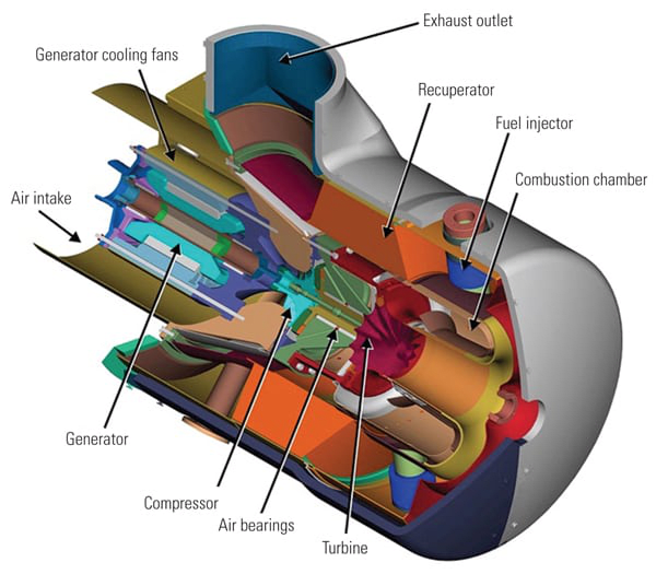
We are designing a 50 kW turbo-generator for use in a hybrid car. This will fundamentally be a turbocharger (+ combustor) directly connected to a PM generator rotor. I have built 5 turbo-thrust engines using turbochargers before, and I worked for 5 years at a company that produced “micro” turbo-fan engines (high bypass ratio, geared fan).
I am very knowledgeable on the thermodynamics, fluid mechanics and operational characteristics of small turbine engines, but am very novice when it comes to power electronics.
Right now, I have a BorgWarner S366 turbo running on a test stand producing thrust only. The next stage of the project is to design, fabricate, and incorporate a PM generator directly on the turbo shaft, sticking out of the compressor inlet side of the shaft (not near the hot stage).
I ran through the thermodynamic calculations, and the turbine should be capable of producing an “extra” 50 kW of power without exceeding the material gas temperature limits. I say “extra” because this takes into account the power needed from the turbine to power the compressor at this operating point. A rotor speed of ~95,000 RPM is needed for this operational point, thought the turbocharger is rated to over 115,000 RPM.
The generator should also be able to function as a starter motor (hence, my statement about “at least 3 phases” on the stator, since only 2 phases here would not be able to spin up the rotor from a stand-still. When acting as a starter, only about 2 kW should be required to get the turbo up to “idle” speed of ~40,000 RPM.
Voltage target at rated power is around 800V since this looks like the new standard in high-voltage hybrid vehicle powertrains.
The electrical output of the stator would likely go through some sort of simple but beefy rectifier, then used to charge some small array of chemical batteries or capacitors.
Thanks!
Max Mitchell

