Continue to Site

Eng-Tips is the largest engineering community on the Internet

Intelligent Work Forums for Engineering Professionals

  • Congratulations KootK on being selected by the Eng-Tips community for having the most helpful posts in the forums last week. Way to Go!

High Stress On Fillets Analysis - Static Linear Analysis 2

Status
Not open for further replies.

binsky3333

Computer
Jan 27, 2020
14
Hi all,

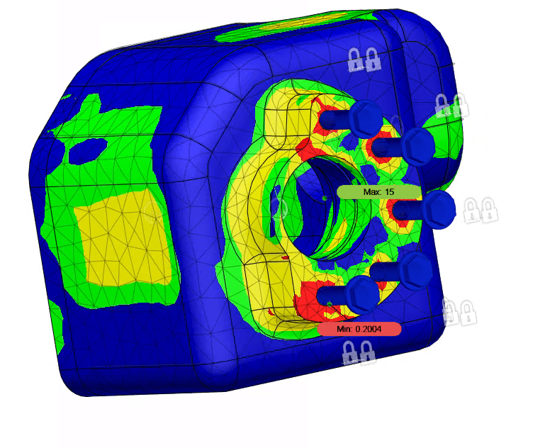
I am posting in hope of someone helping me analyze a high stress that I am seeing on a fillet in my FEA simulation.

For reference I am using Fusion 360 and running a static linear analysis. Everything else in my simulation is perfect except for this one fillet.

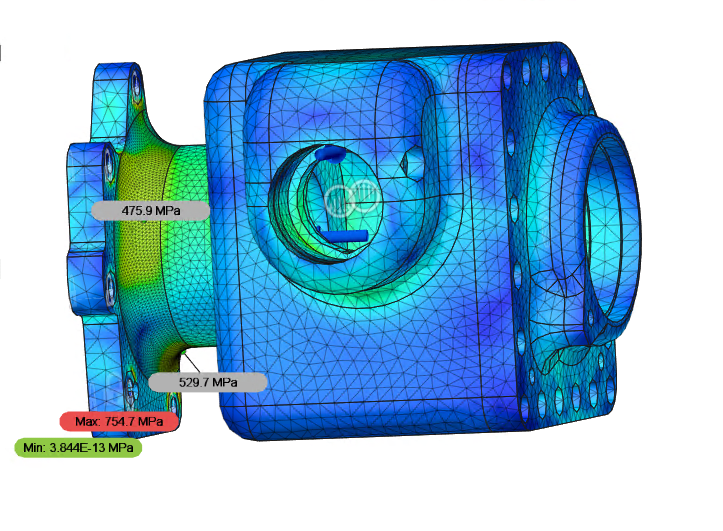
I am simulating with Aluminum 7075-T6 with a 455MPA Yield and 525MPA Ultimate.

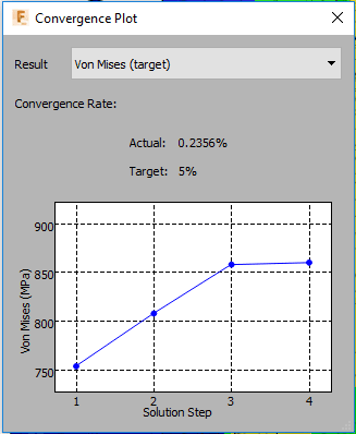
As a side note, my simulation does converge as seen below, so I know this isn't a singularity / hot spot / calculation error.
image_mhyveu.png


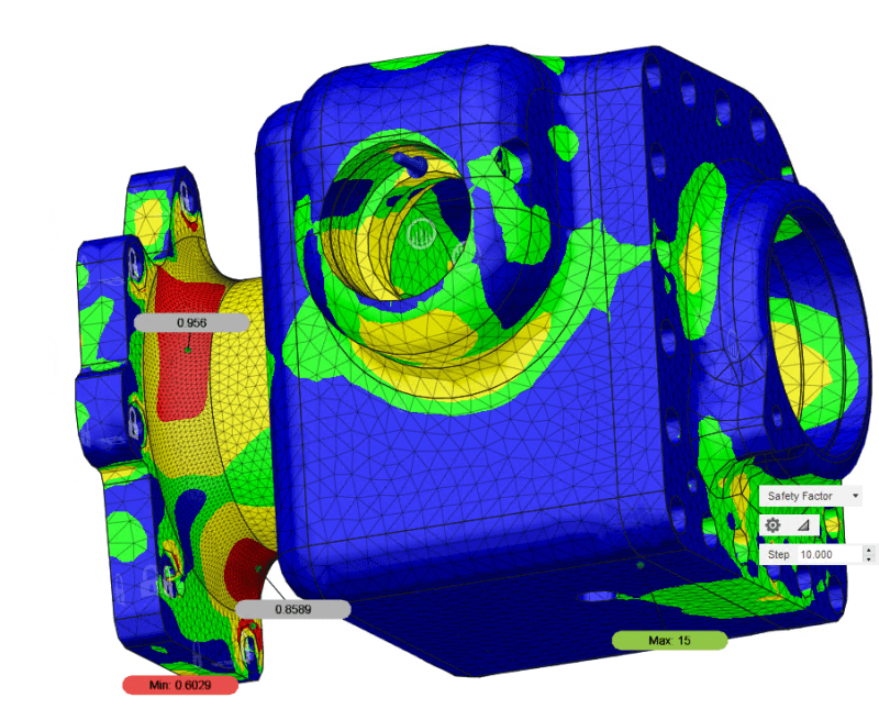
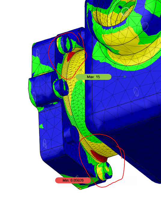
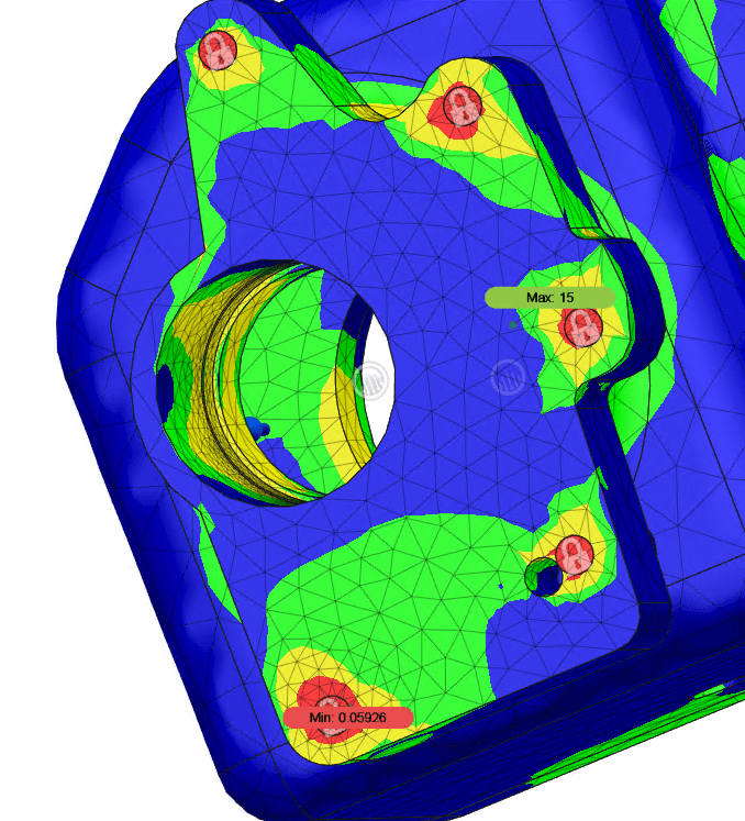
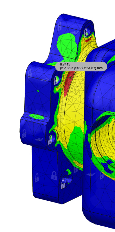
The stress on the fillet is pictured below. It is a 5mm fillet. Making the fillet small makes the stress area longer. Removing the fillet makes the stress area disappear.
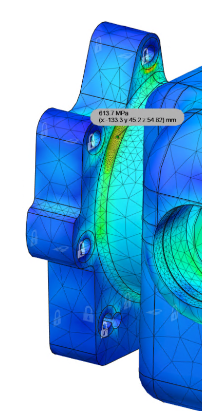
image_glxdya.png

image_zasrry.png


I am confused about this because I see many mixed opinions on how to handle this:

1. Oh just ignore it, its artificial, stresses like that on fillets don't make sense.
2. You need to fix it and make it disappear or except a failure.
3. Since the effected areas volume is so small you'll see a local yield which wont make the whole part fail, but it will fatigue over time. Compared the max stress to a S-N curve to determine how many cycles you'll be able to get out of it.
4. If you are really worried and don't trust any of the above, run a nonlinear analysis.

My personal analysis is leaning more towards number 1 & 3. Such a high stress on a fillet really doesn't logically make sense (I could totally be wrong), especially when the fillets actually bring out the stress in that area. Removing the fillet, the stress in that area goes away too. Since the effected volume is so small, its just a localized yield and those are OK and don't mean complete part failure instantly, just eventual fatigue failure over time.

Hoping someone can provide some insight on my personal analysis and tell me if I'm thinking correctly or not. I'm fairly new to FEA.

Many Thanks!
 
Replies continue below

Recommended for you

5 is given if linear stresses exceed yield.

one way you can infer a "real" stress is to assume the same strain would develop …

FE gives you a stress, strain = stress/E
read this strain onto the real stress/strain curve to see the "real" stress.

In determining fatigue a couple of options open up …
1) do you use the peak (element averaged) nodal stress with Kt = 1; or
2) do you infer a stress concentration, Kt, based on the peak stress and some (guess) as to the nominal stress.
3) maybe repeat 2 with several Kts

another day in paradise, or is paradise one day closer ?
 
Continuing to play around with things...

Now that I have a better understanding on how to analyze these stress concentrations I wanted to do some experimenting.

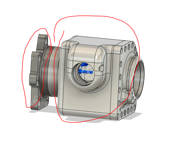
I wanted to be able to make the fillet where I am having those stress concentrations larger. Unfortunately due to the size of the neck (that connects the case to the flange) it made this difficult because anything bigger than a 5mm fillet would cause it to interfere with the bolt holes.

I decided to try and make the neck smaller so that I could make the fillet bigger. This basically just ended up making those stress concentrations on the fillet spread out over a much larger area. I suspect this is because in order to make the fillets larger I had to reduce the size of the neck thus reducing the strength of the neck.

Below are some results from my non-linear analysis.

We can see it didn't really make the stress higher but the area of the stress is way larger. Its no longer a small localized stress concentration.

image_ec7db2.png

image_c0yhbu.png


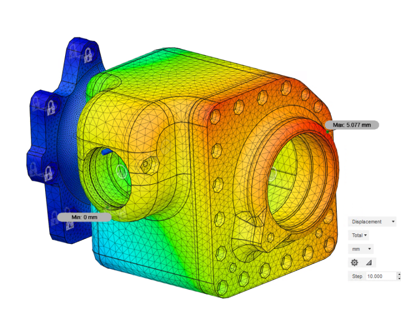
It also made the displacement more than double (before 1.8-2mm)!!

image_swhmjf.png


I have concluded that taking this approach is not going to make things better. I think my best bet is how I had originally with the large neck and small 5mm fillet... and I think that the small local stress concentrations I am seeing there are OK. At least when we are talking about absolute max loading and when there won't be many cycles at that load. I think aluminum will be OK for a prototype and my initial testing, but I don't think its going to take much more than a few hundred cycles at that absolute max load condition, if that. 4340 or 8620 would be a good option, but they're 3x heavy. But honestly, who knows If ill even be getting close to that max load condition.

I still need to do some more strain life chart anaylsis but I am having a hard time finding such charts for aluminum. Anyone have any good sources?

~Matt
 
Honestly, with your issues being so close to the fasteners, I think a lot of your stress is due to having to deal with your fixed boundaries at the fasteners, especially since your fasteners are going to have some give axially due to how long and thin they are. Rather than considering them fixed, I would create a 1D spring element with the appropriate fastener stiffness (such as via the Huth formula), connecting one end to the part, and grounding the other end. In Nastran, I would create this element as a zero-length element right at the interface between your part and the transmission, and then connect this to a second 1D element that goes through the hole and spans the thickness of your part and connect it to both surfaces of your flange via RBE3s, and then make the stiffness of this part such that the fastener load is split up roughly equally to the two surfaces.

Though, it might be easier to just model the fasteners in 3D elements, bond it to the surface of your part, and let the other end be fixed...
 
Hey Countryman thanks for the reply.

Even though Fusion 360 Static Stress does use Nastran behind the scenes I unfortunately don't have access to all of those different element types you are talking about.

Your last sentence about modeling the fastener in the 3D got me curious. I decided to give it a try...

Basically I modeled a very simple bolt with a 22mm head and a 10.5mm shaft (hole is 10.5mm too). I then aligned up everything properly.

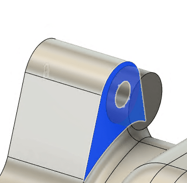
Here is how I setup my contacts.

Between the bolt head and the flange I set that up as bonded.

image_nicjhe.png


Between the bolt shaft and flange hole I set that up as sliding (not sure if this is correct maybe this should be bonded as well?).

image_chv2pj.png


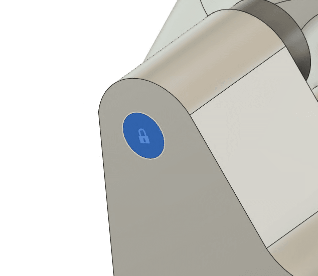
Lastly I fixed the end of the bolt.

image_gskm4i.png


The results were pretty similar in terms of that fillet area vs used fixed constraints.

image_sffife.png


High stress concentrations on the bolts.

image_xtesqj.png
 
Well, that's unfortunate. The only other thing that comes to mind is to see if you can design in some small gussets between the attach flange and neck to take some load away from that fillet. It might be tricky getting in them in such that you can still install the fasteners, though.

If it helps, I've attached some strain life constants I got when I took a class a while back. I don't have a proper reference for these, so use at your own risk!
 
 https://files.engineering.com/getfile.aspx?folder=ef4c2df4-07f7-45b8-b3f5-84ba9c4da5d8&file=Strain_Life_Constants.pdf
Appreciate the strain life data countryman as well as the help you have given me.

I did try adding some gussets on the bottom most portion of the flange as well as one of the sides. Unfortunately it didn't help much :/ and clearance in the areas where I can add gussets is very tight.

One thing that one of my friends suggested to me was to cut the neck in half and basically machine the flange / half of the neck out of steel such as 4340 and then bolt that part to the 7075 main case.

Basically as follows:

image_flkpwy.png


It works really really well and completely fixes those stress concentrations due to the flange and those problematic fillets being made out of steel when I simulate the flange and the main body as bonded.

The issue is simulating the bolts...

The way the fusion 360 bolt connector constraint works is it uses beam elements by having one beam element represent the shaft, where the node ends of the beam element are located at the centers of the circular edges that are used for the head and thread locations. Then at each end of the beam element used for the shaft more beam elements are used to connect to the hole edge in a kind of spoke wheel circular pattern. Those spokes are connected to the 3D solid elements at the hole edge. Since the load is being transferred through an edge, a stress concentration will likely manifest. Like found below...

image_vttpih.png


I could try 3D modeling the bolts and then manually setting all of the preloads & contacts but it becomes unmanageable.

Ill keep plugging away...
 
I'd've thought making it a two piece ass'y would have increased the cost a lot ?

Is there no way to change the fillet geometry ? I'd've thought a simple change to the fillet contour would be cheap to implement ?

Could you shot peen ? probably too expensive ?

Can you benchmark with a successful design ? How do we know that this peak isn't on current designs (which are successful) and so is really a "model artifice" ?

another day in paradise, or is paradise one day closer ?
 
Status
Not open for further replies.

Part and Inventory Search

Sponsor