Eng-Tips is the largest engineering community on the Internet

Intelligent Work Forums for Engineering Professionals

High vibration @1000rpm of a 180kW Ac Motor 7

Status
Not open for further replies.

CelsoSC

Electrical
Feb 7, 2021
37
0
0
PT
Hello, I had to service a Siemens Simovert VC with all three input thyristors shorted.
This VFD is used on an Atlas Copco GA180 VSD compressor.
The fault history buffer showed consecutive overcurrent trips F011.

Suspicion was a mechanical issue, and it turned out that the bearings of the motor were defective.

At the shop, they exchanged the standard bearings with insulated bearings.

It's a Siemens 2-pole, 3x400V, 180 kW motor.

After putting everything in place, I noticed a very strange behavior of the motor-VFD combination.

On ramp-up or ramp-down of the motor, I have a high vibration of the motor at about 1000 rpm with a high current peak on the output of the VFD.

This happens with or without the motor attached to the compressor screwhead.
At other rpm's the motor seems to perform with normal current readings and no vibrations.

What can I check? What kind of motor defect can provoke this behavior?

Thanks for any help!
 
Replies continue below

Recommended for you

Not sure of the cause but the solution is to program 1000 RPM as a forbidden speed in the VFD.
The VFD will then accelerate quickly past the problem speed.

--------------------
Ohm's law
Not just a good idea;
It's the LAW!
 
Increase pulse frequency and check vibration.
Note that above 4-5kHz pulse frequency will begin a derating VFD output current.
What kind of stop is set on VFD?
To check if is a mechanical issue, speed-up motor above 1000rpm and stop VFD (coasting w/o any braking) and check vibration.
 
On ramp-up or ramp-down of the motor, I have a high vibration of the motor at about 1000 rpm with a high current peak on the output of the VFD.

This happens with or without the motor attached to the compressor screwhead.

At other rpm's the motor seems to perform with normal current readings and no vibrations.

What can I check? What kind of motor defect can provoke this behavior?

I think you have good advice of things to check and ways to block.

In terms of what can cause that behavior, it's an interesting problem with no obvious answers.

Everyone is familiar with "resonance" where vibration goes up at a certain speed.

If you can manage to do measure a snapshot of the spectrum to determine frequency while operating near 1000rpm, that may give a clue.

If you can manage to do a coastdown waterfall of vibration as speed ramps thorugh the problem range that would be additional info to check whether the problem frequency changes with speed. Typically the natural frequency is fixed but the excitation frequency usually does change with speed. If the excitation frequency doesn't change with speed (is fixed) that narrows it down to maybe something related to switching frequency (maybe it causes torque excitation components). Changing the switching frequency as suggested by io95 might be a much easier way to check for that particular thing. Also in theory possible are fixed frequency components associated with the input power. If we have a 3-phase full wave bridge rectifier on the input then the ripple frequency is six times line frequency on the dc bus, and that could maybe somehow show in the output (yeah I know it seems like pwm should destroy that, but I hear a lot of people that measure that frequency on vfd driven motors.... I can't count myself as one of those since we have very few vfd's at my plant). And less likely if there is an unbalance on the input side then one times line frequency might show on the dc bus (and again somehow on output). Unbalance on the input is generally less likely but if there's an implication the problem only showed up after replacing some input thyristors then I wonder if one of the replacement thyristors is malfunctioning which coudl cause an unbalance on the rectifier input producing a component of 1x line frequency on the dc bus.

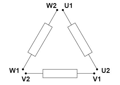
You reported no change between coupled/uncoupled. That is typically a characteristic of lateral natural frequencies but not torsional natural frequencies. (motor tends to have same lateral natural frequencies coupled or uncoupled, but most of the torsional natural frequencies change when coupled to a load.

You reported increase in current at the problem speed (whether coupled or not). That's the one that is of course most bizzare and I have to reach to bizarre scenarios to explain it.
[ol 1]
[li]The most plausible scnenario I can come up with is that you have internal movement of such violence that the rotor is heavily scraping the stator causing a mechanical load. Maybe changing the bearings reduced the rotor support stiffness bringing a critical down that was previously above the operating range. Although that would be a really severe rub to load the motor and I really wouldn't expect this could continue long before there is some other obvious indication of it. [/li]
[li]Even less likely than that, torsional oscillation at a low frequency is causing swings of fundamental current as the rotor accelerates and decelerates. I have a hard time imagining that remains the same coupled or uncoupled though.[/li]
[/ol]
There's probably a lot more I haven't thought of but that's all I can come up with.
 
Hello iop95,
The start and stop are controlled by the Atlas Copco Elektronikon Mark IV Controller.
This compressor has a Siemens 6SE7033-7EG60 VFD, and I don't know this model well. I will have to dig a little more into the manual.
I used to service the Micromaster 440 models on Atlas Copco compressors. And a "problem" with micromaster is that when you change the selection of command source P0700 to do some tests, you lose all BI parameters, and Elektronikon will not communicate anymore with the VFD.

But yes, I will try different pulse frequencies.

I don't have access to another VFD that big at the moment, but I will try to connect the motor unloaded to a smaller VFD and control it manually to rule out the motor or the VFD.

Hello electricpete,

Thank you for your input. I'm sorry, but I don't have access to measurement equipment to do vibrational analysis.
I'm just curious: what frequency range does the vibration sensor need to cover to do frequency analyses on motors?

Yes,depending on the input rectifier design, fixed-frequency components can be more or less present on the output of an VFD.
Less present on pure diode full wave bridge rectifiers and more present on thyristor-controlled 3-phase full wave bridge with DC-Bus voltage control.
Some Schneider Altivar designs have these fixed-frequency components on the output and leave nice patterns on the motor bearings.
Aged DC bus capacitors don't help also.

On this Siemens unit, the thyristor-controlled 3-phase full wave bridge is used to ramp up the voltage slowly to charge the DC-BUS and remains "full open".
The current ripple on the DC bus is also load-dependent. I think when the motor is uncoupled, these fixed-frequency components should be negligible.
 
i was thinking about the rotor stator rub scenario... it would surely create a lot of noise. do you know if the motor creates a lot of noise as it passes through 1000 CPM? if so is the noise anything you can describe?
 
Still no luck with this motor could run it only at 10-12Hz, hitting the current limit at about 130A output of the VFD I could get.

Motor is a Siemens 1LA6 316-4AA91-Z
Δ400V 76Hz 181kW PF0.87 FLA 310A 2665rpm

Connection of the motor on the output of the VFD is U1W2 , V1U2 and W1V2.

triangulo.drawio_oz6bnj.png


I would like to know what happen to a motor if one of the winding is connected in opposite direction, like U1W1, W2V2 and V1U2?
 
Running on two windings, a back EMF will be generated in all three windings.
Rather than being close to the applied voltage, the back EMF in the reversed winding will be opposing the applied voltage.

--------------------
Ohm's law
Not just a good idea;
It's the LAW!
 
Yes, waross is right about that.

And it certainly could cause higher-than-normal current and higher-then-normal vibration (if it runs successfully at all). I think it would do that at any speed, but current and noise generally increase with speed anyway, so maybe you only noticed when it got to the problem speed? (did you ever go above the problem speed and if so what happened there?)
 
Hello electricpete,

Uncoupled I can ramp up the motor from 0 to 3000 rpm (100Hz), with high vibrations and current spikes at about 1000 rpm (30-34Hz).
On ramp-down VFD always trips over-current (310A) at 1000 rpm.
 
It's a Siemens 2-pole, 3x400V, 180 kW motor.

Δ400V 76Hz 181kW PF0.87 FLA 310A 2665rpm

0 to 3000 rpm (100Hz)

These things don't jibe.

If it's 2 pole, 50 Hz/60 Hz, at 76 Hz, the speed will be much higher (4560 RPM) than your stated 2665 RPM.

If it's 4 pole, 50 Hz/60 Hz, at 76 Hz, the speed will be lower at 2,280 RPM.

Post the photos of nameplate and the motor terminal board.

I have seen phase starts and ends of winding wrongly connected at terminal board with overcurrent, noise, vibration etc. happening.

Muthu
 
@CelsoSC,
Just program the VFD to skip the 1000 rpm operational speed to protect your motor bearings. We do that also in running our GT which has a 1st critical speed of 1300 rpm.
 
Hello edison123,

You are right, it's 2255 RPM. Nameplate is hard to read.

IMG-20230526-WA0006_acygce.jpg


There is no motor terminal board, 12 high flexible yellow wires are coming directly from inside of the motor. Cable marking U1 U1 U2 U2 V1 V1 V2 V2 W1 W1 W2 W2.
 
This motor has 400V rated voltage at 76Hz base frequency.
Check if parameters P101=400 and P107=76. Check if all motor parameters have correct values.

What values are at P115, P318, P319, P325, P326 and P330?

Overcurrent trip on ramp-down it's normaly related to too short braking time with high inertia load that lead to high DC bus overvoltage > onvercurrent or too high DC current braking.
DC braking is enabled?

 
Hello iop95,

This VFD is used on an Atlas Copco GA180 VSD compressor, VFD and motor setting was matched at factory and no modification where made to the parameters of the VFD.

P101 Mot Rtd Volts = 400
P107 Motor Rtd Freq = 76
P115 Calc MotModel = 0
P318 Boost Mode = 1 Volt. Boost
P319 Boost Amps = 155
P325 Boost Volts = 4.3
P326 Boost End Freq = 15.20
P330 V/Hz Mode = 0 Linear
 
Hello edison123,
Without opening the motor is there a trick to discover the phase starts/ends of the winding?

On transformes, especially encapsulated, I use a sine wave on the primary and feed the signal to one channel of an oscilloscope and check phases of the other winding with another channel of the oscilloscope.
 
Status
Not open for further replies.
Back
Top