Continue to Site

Eng-Tips is the largest engineering community on the Internet

Intelligent Work Forums for Engineering Professionals

  • Congratulations KootK on being selected by the Eng-Tips community for having the most helpful posts in the forums last week. Way to Go!

Highest Recommended Edge Distance 3

Status
Not open for further replies.

Stress Engineer

New member
Oct 8, 2017
2
Dear Folks,

We all know the recommended edge distance should be 2d. I would like to know what is maximum edge distance allowed in case of

(i) metallic components

(ii) Sandwich Floor Panels

Thanks in advance
 
Replies continue below

Recommended for you

minimum edge distance for composite should be 3D.

I don't think there is a maximum ... there could be collateral design issues with extreme edge distance (like the plate lifting up, causing problems). Mostly it's just wasted (ineffective) material.

another day in paradise, or is paradise one day closer ?
 
The min is 2D for metals. I think the standard is 3D for (most) composites.

There's no general max for metals because it would be (as rb notes) mostly dependent on the configuration and loads.

For a composite floor panel, you would not want too much E/D mostly because you want floor panels to create a decent barrier for liquids, support walking loads, etc. You want enough fasteners to transfer loads and keep the panels in place with controlled deflection. Also, too much E/D could cause significant fretting as the floor structure flexes.

 
A couple of other points to consider:

1. Some additional edge distance might actually be beneficial since there is typically a layer of sealant between metallic structures. The sealant is somewhat effective at transferring load, so if there is additional surface area of adhesion, theoretically the outer row severity factor could be mitigated to some degree.

2. How would the extended material past the outer row of holes affect the interaction of the two layers in secondary bending? The out of plane bending of a joint from eccentricity could be affected by the amount of edge material.

3. Be aware that the edge distance could affect the structural inspectability. For example, Airbus SRMs like to specify ultrasonic (UT) inspections of repair doublers. This involves placing the probe along the doubler edge and sending a signal in toward the fasteners. The NDTM will have a calibaration standard such that the quoted detectable flaw length is only valid for a certain edge distance, since this changes the signal transmission distance.

I would say in that case the ED is limited by the inspection capability.

Keep em' Flying
//Fight Corrosion!
 
Stress engineer...

Nominal should actually account for manufacturing tolerances... and good weight management... with an understanding that MMPDS/MIL-HDBK-5/corporate design manuals define Fbru/y for 1.5-e/D and 2.0-e/D... ONLY.

Any e/d lower than 1.5 runs the risk of 'low-Fbru/y unknowns'... without testing.
Any e/D higher than 2.0 general does not add substantial strength and may/may-not provide added fatigue margin

These tables always assume good hole location/drilling/reaming practices.

I have worked in different companies/orgs. The standard I go by for 'best-personal-practice [unless otherwise defined by technical manuals or drawing/corporate standards] is as follows...

Designed edge distance = (2.0-D) + 0.060" [KISS] or 0.062" or 0.063" (take-your-pick)... [+/-0.030" Mfg tolerance]

So... for a 3/16-D-nom fastener = 0.187"(*2) + 0.060" = 0.434"-nom (+/-0.03" Mfg tolerance) or 0.437"-nom (+/-0.030 Mfg tolerance)

NOTE. This ROT[thumbsup2] is typical for protruding-head, 100-Deg flush-shear-head [NAS1097] and shallow 100-Deg flush-tension-head [MS20426] style rivets and Hi-Loks; BUT NOT for 100-Deg flush-deep/wide-tension-head bolts/screws (recess-drive) intended for occasional removal/re-installation [MS24694, NAS517, etc]... where 3D really is usually more appropriate.


Regards, Wil Taylor

o Trust - But Verify!
o We believe to be true what we prefer to be true. [Unknown]
o For those who believe, no proof is required; for those who cannot believe, no proof is possible. [variation,Stuart Chase]
o Unfortunately, in science what You 'believe' is irrelevant. ["Orion", Homebuiltairplanes.com forum]
 
Perhaps it just amplifies WKTaylor's last point, but I'd like to add that a large countersunk head in the edge fastener removes an amount of the material between the hole and the edge. With small CSK heads and thick plates, there is no issue, but the bigger the head gets, and the thinner the sheet gets, the difference becomes substantial. So with a big CSK head, what you may think is "2D" is actually less... sometimes a lot less.

STF
 
LiftDivergence... CAUTION...


Alas... sealant has exceptional value for pressure/fuel/etc-sealing and for vastly improved corrosion isolation between dissimilar materials [especially with corrosion resistive additives]... but actually has a NEGATIVE value even when properly applied to a structural joint.

Sealant is NO effective shear-load capability, relative to tight fasteners in metallic structure.

Perfectly applied, sealant crushes-out of the joint ['squeezes-out'] while a tiny bit remains between parts filling tiny gaps. The squeeze-out is then filleted along the part-joints for added isolation. In this case perfectly applied sealant allows maximum structural tightness and fit-up. for nominal static strength and fatigue durability.

However, most sealant is imperfectly applied... the viscosity ['goopieness of the wet sealant'] and excessively thick application and slow installation of [temp and permanent] fasteners to collapse/crush the joints tight often results in joints that are 'structurally gapped' a few thousands... and the fasteners are essentially 'shanked'... with 'no-strength' cured sealant filling the gaps. In this scenario sealant break-down due to micro straining of the structure/fasteners is inevitable.

Early testing of fay-surface sealing with highly viscous [fillet] sealant showed major strength/fatigue reductions.

Sealant for fay-surfaces had to be reformulated to have MUCH lower viscosity resulting in better [not-perfect] fits between major structure elements and far-easier 'squeeze-out' of excess sealant. For larger assys 'long-working life sealants' [24, 48, 96 etc hour] sealants are mandatory. In some design manuals/guides there is at-least a 10% 'knockdown-strength factor' and a significant [compounded] 'fatigue-life knockdown factor' [varies].

NOTE. When integral tanks were introduced, the structure and all fasteners were assembled 'dry'. Significant gaps/holes were simply 'pressure pack-filled' with injected sealant; and then the entire structure was tediously filleted/over-coated with sealant on the pressure/fuel side. Needless to say pressure and fuel leaks were pretty common. In this structure/sealing assy method, the negative effects of fay surface sealant did not exist.

NOTE. In most large commercial acft made to day, this is still the standard-practice...however fabrication/fastening methods/techniques have become very precise resulting in high pressure-tightness thru superior joint fits and leak-proof fastening... tedious hand-sealing [to a lesser extent] is still needed. Also, from a practical perspective: sealant is smelly, messy, impossible to get-out-of-cloths and requires PPE. Machines/tools [drill motors, fillet guns, drill/reamer-bits etc] have to be frequently cleaned and clothing is a lost-cause [I've ruined shirts/pants with just a slight smudge/drip of polysulfide sealant].

NOTE. When assembling small/confined structure [GA, fighters, etc], fay surface sealing is usually employed with careful attention to detail [I don't have time to discuss here]... at risk of really screwing things-up...

Gottagetbacktowork

Regards, Wil Taylor

o Trust - But Verify!
o We believe to be true what we prefer to be true. [Unknown]
o For those who believe, no proof is required; for those who cannot believe, no proof is possible. [variation,Stuart Chase]
o Unfortunately, in science what You 'believe' is irrelevant. ["Orion", Homebuiltairplanes.com forum]
 
Wil,

Thanks very much for the response, your words of caution are well taken. I always appreciate your depth of knowledge, I've learned a lot from your posts and this is no exception. For the record, just to note my statement was not entirely baseless on my part, I was thinking of a few papers which I will note below. Obviously I'm not trying to reduce any of your input above - I think if anything this discussion just does a good job highlighting the fact that this is not necessarily a simple issue at all.

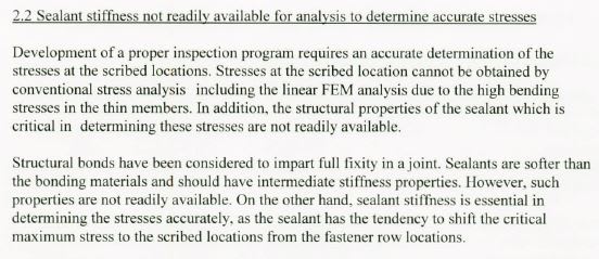
In my experience with post-production support for 737 classics, one thing we run into a lot (obviously) is the scribe issue. So in the past I have endeavored to become as knowledgeable as possible on the issue. I recall several publications highlighting research and testing being done regarding the stiffness of the sealant. The main argument was that although not as effective as a structural bond, there was some shear capability which could lead to a change in the peak stress location. The concern was that if a scribe was made while removing sealant, maybe some disassembly of the lap and repair work was done, and then the structure was re-sealed, you would not only have a scribe, but due to the sealant stiffness, the peak stress location may actually be located closer to the scribe line, away from the outer fastener row. Below is an excerpt from the 2007 meeting of the international committee on aeronautical fatigue (ICAF) which discusses this a bit more:
3_va15wb.jpg


Some discussion in [I am not, nor have I ever been employed by Boeing]:
Boeing SDT Document, "Development of a Method for Damage Tolerance Analysis for Scribe Marks Adjacent to Fuselage Longitudinal and Circumferential Splices"
de Rijck, "Stress Analysis of Fatigue Cracks in Mechanically Fastened Joints"
I think this may have also been discussed in the 2004 737 classic conference on scribes

This is why I mentioned theoretically, if you had a well adhered sealant, you could theoretically shift the peak stress away from the row of holes by some amount. However, I did not, nor would I, recommend attempting to take advantage of this in an analysis.

Also potentially interesting, although dealing with structural bonding, which is different, are some other resources:

DOT/FAA/CT-95/25, "Strain Fields in Boeing 737 Fuselage Lap Splices: Field and Laboratory Measurements with Analytical Correlations", in which bonded and non-bonded joints are compared
DOT/FAA/AR-98/33, Uniaxial and Biaxial Tests on Riveted Fuselage Lap Joint Specimens - simlar


Keep em' Flying
//Fight Corrosion!
 
LiftDivergence.

Sealant is a true elastomer with very high-elasticity/low-stiffness

Epoxy adhesives on the-other-hand have very high-stiffness/low-elasticity relative to elastomers [~1000X].

However the shear modulus-E [stiffness] of most adhesives [~0.3X10^6-E] pales to the shear-modulus of aluminum [factor X 10.0X10^6-E] or Titanium [factor X 16.0X10^6-E] or Steel [factor X 30.0X10^6-E]. ['factor X' = I'm lazy and not checked MMPDS].

There is some (+) test/analytical evidence for benefit of adhesives in fastened joints for crack growth retardation [especially for battle damage 'impact/detonation shock'] and along free-edges [but NOT necessarily fastener-holes] and enhanced pressure sealing durability. Also, adhesive joints tend to resist 'peeling' [tension-shear loads] at/along free-edges [exposed laminations].

The GD F-106 and the F-16 designs both employed riveted/adhesive-bonded structure that has been proven [tested] to have superior toughness/durability/leak-resistance relative to 'fay sealed joints'.

It took many years for integral fuel tanks to become 'accepted' in general aviation. In 1972 my dad approached John Thorp with need for added range... and a monumental 'how-do-I-do-this with the T-18?' question'. JT responded, eloquently, with proposal to wet-seal the entire outer wings [~40 Gal capacity each] and the inner-wing leadings edges [~15-Gal capacity each. We were astonished [I was a college Aero student at that time and had just heard of integral tanks]. what he proposed seemed like the magical solution to the dilemma... but would require redesign of these areas of the wings to accommodate the sealing... which he provided fairly quickly. When he provided the redesign/road-map for integral tanks and access doors and plumbing and vents, etc... we came to find out that he was already a master of integral tank design in GA acft [Wing Derringer and a few others] for added fuel capacity. we also came to find-out that he had already put thought into the needed re-design/revisions because of a 'casual conversation' my dad had with him a year or two prior about extending the range of the T-18... JT was ALWAYS very thoughtful [forward-thinking] and was NOT one to be taken by 'a homebuilder's surprise/serious question' IF/WHEN it became a reality. Which it did.

Essentially the integral tank redesign... of wings that were never intended to carry fuel... included NOT just the elements of sealing and plumbing, but also the added fuel-loads/slosh/asymmetry and joint improvements [reduced fastener spacing, thickened/stiffened ribs/skins a few added stiffeners, etc] to keep the joints tightly together. Also there were practical aspects that mandated several added structural access doors [lower skin, NOT upper skin]. During construction the structure was fitted/mate-drilled-together 'dry'... then disassembled, cleaned and re-assembled 'wet' with a fay-surface [low-viscosity long-working-life] sealant... and great effort due to the 'dry fit-up-of-parts'... using early 1970s version of PS-890. Lucy my sister [NOT!]... her arms/hands were the ideal/only fit inside the wing for fillet-sealing/packing areas of concern such as the fittings and outer ribs... but she will never forget the sticky mess and sulfur smell of the sealant and cured rubber under her fingernails].

BTW... after this T-18 wing re-design was revealed [mid 1970s] there was a mild 'sh*t-storm' of controversy regarding wet-fay-sealed integral tanks in thin/light-weight sheet metal structures. HOWEVER one thing I came to realize is that John Thorp... a consummate aero engineer... 'knew the rules to break the rules' and created a sound design for dad's acft [N455DT].

Regards, Wil Taylor

o Trust - But Verify!
o We believe to be true what we prefer to be true. [Unknown]
o For those who believe, no proof is required; for those who cannot believe, no proof is possible. [variation,Stuart Chase]
o Unfortunately, in science what You 'believe' is irrelevant. ["Orion", Homebuiltairplanes.com forum]
 
Status
Not open for further replies.

Part and Inventory Search

Sponsor