Continue to Site

Eng-Tips is the largest engineering community on the Internet

Intelligent Work Forums for Engineering Professionals

  • Congratulations GregLocock on being selected by the Eng-Tips community for having the most helpful posts in the forums last week. Way to Go!

Hip beam hand calcs

Status
Not open for further replies.

Marc Rogue

Structural
Jul 30, 2021
19
Hello guys,
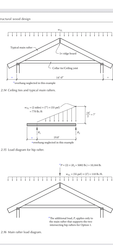
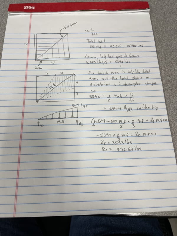
Just recently embarked into wood design. Reading up on a wood design book I came across the design of a hip beam but the calcs proposed in the book don’t jive well with me and I wanted to get someone else’s opinion. I know books get revisions so it should be ok but the problem is their solution yields more total load than it’s actually there. Please look at the images and let me know your thoughts on it.

Thank you
76F20BC8-3F04-445A-B1CB-C7DA793445A8_kwquvt.jpg
089AF987-7339-4731-9A94-4C5A16E21D20_loc0qd.png
 
Replies continue below

Recommended for you

At 55 psf, their math checks out to me? 55*14=770 plf. Tapering down to zero at the wall corner.
 
@jayrod, my problem number one is that the shaded area isn’t a right angle triangle so to assume it is makes the dist load greater than it really is, No. 2 and my biggest concern is that based on the way they approached the dist load they end up with more load than 55x14x14=10780lbs
 
It should be 55*14 x 0.707 = 544 plf tapering down to zero on a 19.8 ft long member = 5385 lb total or 3590 at the top and 1795 at the bottom - so basically what the OP said.
 
@xr250 that’s a way of doing it 55x14x14/19.8 to lower the load onto a longer span
 
Ugh, I see my mistake. The spacing of the rafter reactions on the beam isn't the same as the rafter spacing. I couldn't understand where the 0.707 came in until the lightbulb went on.

That being said, I'd have no arguments with being overly conservative on these things and use the higher amount. I've seen many hip beams sagging.
 
The .707 it’s just reducing the 770 over 14’ to 19.8’
14/19.8=.707. So are we in agreement that the book may be wrong
 
As I see it, the book is wrong. The load it calculates is appropriate for the 14' span, but the same load is distributed over 19.8ft on the hip. On the hip, it's not 55psf * 14 = 770 lb/ft, it's 770 lb/ft * cos45
 
An easy way to see what's going on is to look at the beam that is horizontal in plan which spans 14 feet and has rafters spanning perpendicular to it. They calculated the load correctly for that beam using a tributary width that varies from 7' to 0' (7'*55psf = 385plf). The loading for the hip beam should be double that (since it is loaded on two sides), but it has a span that is 19.8' instead of the 14', so just adjust accordingly (2*385plf * 14'/19.8' = 544plf).

Structural Engineering Software: Structural Engineering Videos:
 
I agree the book is wrong. But wrong on the right side of wrong.
 
Fig. 2.14 shows a dimension of 14'-0" o/o wall, which should be 28'=0".
Fig. 2.16 shows a point load of 10,164# plus a uniform load of 110#/' on the main rafter.
I believe that the point load should be 14*14*55(2/3) = 7187# and the uniform load should be 55#/', representing one foot of tributary area, because one foot has already been included in the point load.

BA
 
Sorry BART... I didn't run through the numbers. I was only looking at the triangular load distribution, which I've always used.

Rather than think climate change and the corona virus as science, think of it as the wrath of God. Do you feel any better?

-Dik
 
Something you may or may not know - The pitch of a hip ridge board is the main pitch divided by the square root of 2.
Knowing that can sometimes be handy when figuring things.
 
Status
Not open for further replies.

Part and Inventory Search

Sponsor