Continue to Site

Eng-Tips is the largest engineering community on the Internet

Intelligent Work Forums for Engineering Professionals

  • Congratulations waross on being selected by the Eng-Tips community for having the most helpful posts in the forums last week. Way to Go!

Historic Clay Masonry Compressive Capacity 2

Status
Not open for further replies.

Ben_StructEng

Structural
Jan 29, 2021
9
Hi All,

I'm in Australia and I'm currently trying to justify a significant concentrated load applied from a steel beam to a 110mm thick existing clay masonry wall.

The building was built in approximately the 1950's-1960's and is vertically supported and laterally stabilised by many 110mm thick clay brick walls. One of the walls is to be removed and replaced with a steel beam over, which is going to be supported on the 110mm thick walls with a bearing plate.

I can justify the masonry capacity to AS3700: Masonry Structures if I assume 20Mpa unconfined compressive capacity and a mortar class of M3 or better, though this is likely to be unconservative due to the age of the building.

What I am after is some guidance on clay masonry historic unconfined compressive capacity (in Australia - In particularly Sydney) and some information on the typical mortar mixes of that era (and other era's) that allows me to get some confidence in the actual properties of clay masonry in historic buildings.

I'm not the first person in the world to have specified a new beam in replacement of a masonry wall and assumed some properties for the existing, though where is everyone getting this historical information? And how are they relying upon it without testing?

If I need to get into testing, it will likely cost the client more than what it is worth, and re-framing the system to dump less shear in one location is not always viable. Nor is adding steel columns/new engaged piers etc. and having other issues like slab punching shear etc. at their base.

Can anyone advise on this?

Thanks.
 
Replies continue below

Recommended for you

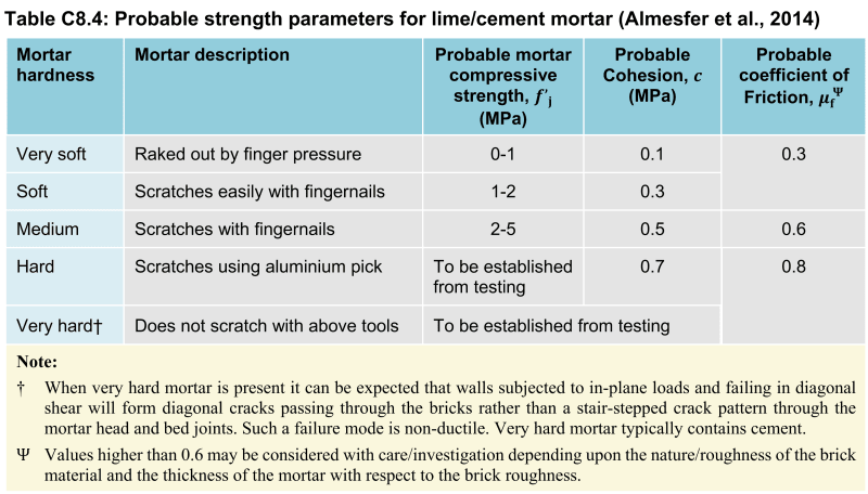
Ben, there are some tables in the C8 part of the NZ assessment guidelines that I'd imagine are quite universal. They are based on simple on-site assessment techniques which any engineer can do on site. See section C8.7.2 within the C8 PDF downloadable from here.

I'd imagine using similar benchmarks you could bound both the mortar strength and clay brick strength to give you some confidence in selecting a conservative value for design checking.

image_prx3rf.png

image_mwoas6.png
 
Thanks Agent666. That's very helpful.

I suspect that in NZ due to seismic activity that your usage of masonry for load bearing elements is quite limited, however the principles for determining basic compressive strength for Mortar and Clay masonry should be somewhat universal.

The scratch test as you've mentioned isn't always going to be able to be applied on a first inspection as many of these older buildings with load bearing internal masonry walls are rendered, so I guess there will always need to be a second inspection if you don't have the ability to remove the render at that point in time.

AS3700 here in Australia does not specify a non-invasive testing method for masonry compressive strength which is unfortunate, so I guess it's back to engineering principles and judgement. Referencing this NZ document will be very helpful.

Thanks again.

Ben
 
Ben_StructEng:
While various codes, stds. and research papers have some avg. strength tabulations like Agent666 has shown, or min. strength values for design, given a brick and mortar combination, the variability of the materials and workmanship have usually dictated the higher design strengths be determined by prism tests of the actual materials and methods used. That 110mm thk. wall is also a fairly thin wall when it comes to a concentrated beam loading, a masonry jamb or column loading. Could you build brick piers at each beam bearing point and key them into the existing wall for better lateral distribution of the load? Or, could you frame the jambs with a 5” steel channel. There are also some testing methods, very thin jacks which will fit within a mortar joint, which allow a testing lab to test the wall strength in-situ. Could you saw cut some test prisms out of the wall area to be removed? You might also put horiz. joint reinforcing in a number of the joints immediately above the steel beam to make the new wall above act like a deep beam, and span out further than the opening jambs, onto the existing wall below.

Ben, I hope you don’t mind my high jacking your thread for a moment…
Agent666, you were right on the money the other day with your posts on that heavy-haul canti. beam problem. But, the guy just wouldn’t listen or think about what you said, he was just too invested in his wrong headed thinking. That was going so far off base, with much inappropriate weld formula manipulation, that I just decided not to stick my oar in that water. If he wants that to work, he better be able to transfer 800kN in tension btwn. the two beams at the outer end of the top beam, and 450kN in compression btwn. the two beams at the inner end of the lower beam. Then, there are plenty of other details to be worked out too. His first error was trying to reuse the existing beam and adding flg. cover pls., etc. He should have just picked a proper beam for the job and been done with it.
 
I must admit I seem to have glazed over the fact that the wall was 110mm and missed it in the initial read through, that makes me a little nervous to be honest. Most of my NZ experience is limited to multi-wythe walls, 2/3 bricks thick and fairly robust for adding additional loads or creating openings.

The actual load wasn't mentioned. But the stability of the wall would need to be reviewed. I kind of think going to some posts or a portal is a good way of avoiding the issue and giving you some piece of mind. Disguise them with linings or reuse some of the original bricks to create a pilaster around the posts.

It's the type of thing having an end of a skinny wall with point load from beam, and well you could imagine giving it a good smack with a sledge hammer and have it come down as it doesn't take too much to destabilise things.

Also don't forget about reviewing the foundations for the additional load at ends of opening. Often these older brick structures in NZ at least just have a pile of bricks at the bottom slightly wider than the walls.


dhengr, yeah guilty of trying to simplify things for them in that post, as an engineer I'm all about making my life easy and avoiding unnecessary complications that some contractor can mess up more than expected, this generally also makes the clients life easier!
Working around unnecessary constraints often seems easy enough at the start, but sooner or later in a fair number of cases you'd be better off starting again as things get harder & more expensive fast. I often tell the younger folk round these parts, if you start out easy you end up at best at hard, if you start out at hard, you often end up at impossible. I have not been back to re-read that thread after seeing the last reply to mine where I got the feeling they didn't really understand my suggestion to simplify it and start thinking about where the loads want to go. May have to revisit it if they are still barrelling down the road on assessing weld groups when the only effective bit was the stiffest bit at the ends.
 
Thanks for your comments guys,

Perhaps it is better to use a live example of a project I'm currently looking at....

The building was built in approx 1950's to 1960's as described in the first part of the thread and my client wanted to investigate a couple of options.

Upon calculation, the reaction forces for both options are very high and I cannot justify a 110mm wall to work on its own, regardless of the other issues mentioned above. I had therefore looked to introduce a brick pier at each end and tie to the existing brickwork with remedial ties.

I can then in a round about way justify the reactions on the Brickwork by calculating the individual pier capacity and then the 110mm wall capacity and combine to get the overall capacity.

The first scheme (Scheme 1) has reaction loads of 185kN ULS, which provided I can achieve a brick unconfined compressive strength value of 20Mpa and Mortar class of M3 equivalent, then it works fine.

The second scheme is a bit more tricky as the loads are quite a bit higher at 275kN ULS, which I can justify by having a T shaped Bearing plate at the ends of the beam with full height web stiffeners to engage the full area of the bearing plate. The bearing plate needs to cover the whole 230x230 pier area + an additional length of the 110mm wall behind (Approx 150mm length additional each side). This provides the steel node stiffness to ensure I can achieve the bearing.

In terms of where the loads go. When the beams are supported at the ends of the property they will disperse into a long wall along the end of the building, which is easy enough to justify. The other end it concentrates on a much smaller length of wall, so I have caveated this version so that it is only validated if I am able to inspect the property below, which I wasn't able to do at the time. So that bit is TBC I guess for now.

In terms of adding a steel column. I would absolutely love to, but I'm nervous about dumping the baseplate load onto the slab below, which has unknown properties and will potentially have a shear or punching problem, depending how the baseplate is detailed. I've seen details where you fix the side of the column to the masonry to try and disperse the load, though I'd have thought that the stiffer load path would be straight to the column base?

The one final thing is global building stability. I'm removing the last long shear wall in the building, however there is an adjoining property to the left side of the building, linked by the floor diaphragms, with a number of shear walls in that same plane, and the fact this is a 4 storey building, I am on the 1st floor and can justify the amount of remaining walls are satisfactory, despite the added eccentricity to the shear centre. A portal frame would help a bit and provide a feel goof factor, but again I'm a little nervous of the above point.

So with all that said, I am heavily reliant on getting some good results from the existing Masonry (at least 20Mpa unconfined compressive capacity), which seems to be possible from that NZ document though may not come back positive one I go and inspect again without the render on the bricks (another inspection needed for that).

So if you guys have any tricks up your sleeve to a) help me sleep at night and b) is cost effective to the client, I would be very much appreciative.

Ben


 https://files.engineering.com/getfile.aspx?folder=4ac4b13c-1f91-4edf-b9a7-51505120447e&file=SCHEME_1_AND_2.pdf
By the way, I do like the idea of adding bedding reinforcement to get a better than 45 degree angle of dispersion. Perhaps that's something to add in regardless? Not sure how easy it is to apply to existing?
 
Status
Not open for further replies.

Part and Inventory Search

Sponsor