Continue to Site

Eng-Tips is the largest engineering community on the Internet

Intelligent Work Forums for Engineering Professionals

  • Congratulations SSS148 on being selected by the Eng-Tips community for having the most helpful posts in the forums last week. Way to Go!

HOLE AS PRIMARY DATUM OR NO?

Status
Not open for further replies.

durablack2

Automotive
Jun 25, 2013
58
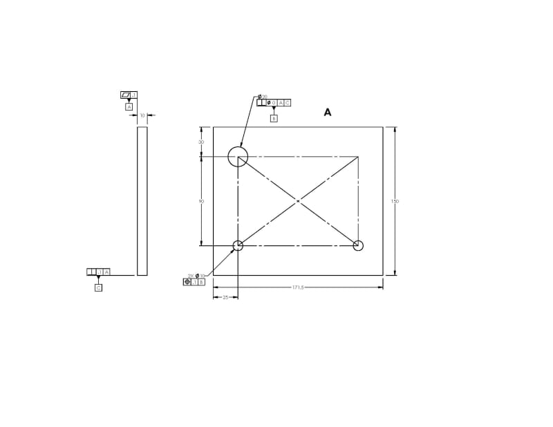
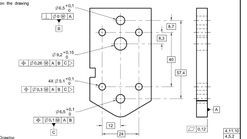
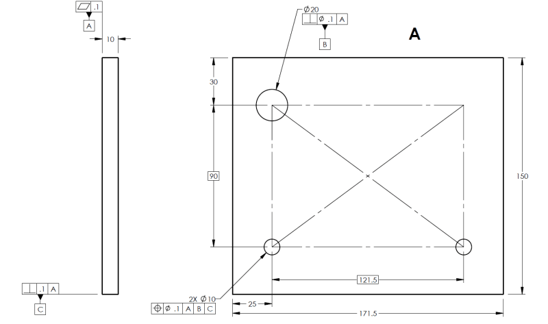
I have a part that is stamped from sheet metal. There are about 6 rivet holes that should be referenced off 1 larger hole for a pin that is about 25mm in diameter. I have made an example of a similiar part that displays the several methods for identifying the datums on this part. The edges of the part do not really matter that much so I know these should not be the primary datum. Should the 25mm hole be primary datum and bottom surface of sheet metal be secondary? Or is it best practice to make the bottom of a sheet metal part the primary datum, and call out the 25mm hole as secondary datum, and assign perpendicularit? OR is it better to use the bottom plate of sheet metal as the secondary datum and call out perpendicularity to axis of 25mm hole?

Which, if any, are correct?
 
 https://files.engineering.com/getfile.aspx?folder=13242904-83ca-4960-860a-c6799a19566d&file=GD&T_PART.pdf
Replies continue below

Recommended for you

Figure A is the most robust but you'd still need a tertiary datum to stop rotation of the two hole pattern around datum feature B.

John Acosta, GDTP Senior Level
Manufacturing Engineering Tech
 
Ok, perfect. So like this, correct?

PART_2_A_qyfzi3.jpg


Or would I limit rotation by making another hole a datum, like in the example below?

Capture_ole3my.png
 
durablack2: Figure 4-15 from Y14.5-2009 is not a "complete" drawing. It does NOT locate the datum B from the edges of the part.

Your "so like this" drawing is close, but a few things are missing. The left edge of the part in the plan view needs to be a datum, I'll call it D

Your 30 diameter datum B hole would be positioned to datums A | D | C with BASIC dims from those datum features

The two holes would be positioned A | B | C with BASIC dims as well

Zero positional and orientation tolerances can only apply with the MMC modifier - you have to have M inside circle after the "0"

Hope this helps

Certified Sr. GD&T Professional
 
durablack2:

I made an incorrect statement "Zero positional and orientation tolerances can only apply with the LMC or MMC modifier - you have to have M inside circle after the "0"


Certified Sr. GD&T Professional
 
For your first picture,
Change datum feature B control to |PERP|dia 0.1|A|
Change the feature control frame on the lower left hole. |POS|dia 0.1|A|B|C|

You now have a datum reference frame that originates at datum feature B and is oriented to C. Now locate the OD to that datum reference frame.

John Acosta, GDTP Senior Level
Manufacturing Engineering Tech
 
I see mcski replied while I was replying.

His way works too but it requires a datum that I don't feel is necessary. It also reflects a different design intent than mine but there's no way to know which one is correct.

John Acosta, GDTP Senior Level
Manufacturing Engineering Tech
 
Ok, I think I almost have it... I'm not exactly sure what you mean by locate the OD to the datum ref frame though? Can you explain more? Thanks for all the quick help so far!

Also, John, I think your approach is better for this part because I do not really care much about the outer edgesd of the part. It just sits on a panel. The holes are what need to line up. Correct me if I'm wrong though.

PART_3_nxty5e.png
 
Add a profile of a surface callout, all around, to the OD of the part.

|PROF|X.X|A|B|C|

Change the 30, 25, 171.5, and 150 to basic dimensions and that's it. Keep in mind datum feature C will only have half the available profile tolerance.

The only thing I'd fix from here is making the dimension and tolerancing format correct. For example, it's 0.1, not .1. Numbers smaller than 0 must have a leading zero.

John Acosta, GDTP Senior Level
Manufacturing Engineering Tech
 
Tick, what is the question?

John Acosta, GDTP Senior Level
Manufacturing Engineering Tech
 
The question is why is there a diameter modifier on a perpendicularity callout?
 
Because it's applied to a cylindrical feature of size.

John Acosta, GDTP Senior Level
Manufacturing Engineering Tech
 
It means the axis of the hole has to be perpendicular to the primary datum.

John Acosta, GDTP Senior Level
Manufacturing Engineering Tech
 
See figure 6-13 in the 2009 standard for one example.

John Acosta, GDTP Senior Level
Manufacturing Engineering Tech
 
Never seen it. It may be legit, but it piques my sensibilities. Usually see position in this case. Six of one...
 
There's no locational constraint of B to A so position would be incorrect to use. The only relationship B has to A is perpendicularity so that's the one to use.

John Acosta, GDTP Senior Level
Manufacturing Engineering Tech
 
Disagree. With a single normal datum, position effectively becomes perpendicularity but is still valid. (So I was taught, perhaps sensei was wrong?)
 
Specifically what in my statement do you disagree with?

It's not that using position to only control the perpendicularity of a single secondary datum feature is valid, it's that the standard doesn't expressly prohibit it, thus some people think that's validation. It's not.

It makes no sense to use position in that manner, especially since you already know that all you're trying to control is perpendicularity. Why wouldn't you just use perpendicularity?


John Acosta, GDTP Senior Level
Manufacturing Engineering Tech
 
Status
Not open for further replies.

Part and Inventory Search

Sponsor