Continue to Site

Eng-Tips is the largest engineering community on the Internet

Intelligent Work Forums for Engineering Professionals

  • Congratulations KootK on being selected by the Eng-Tips community for having the most helpful posts in the forums last week. Way to Go!

Hole pattern along Belt

Status
Not open for further replies.

S-eng

Mechanical
Jul 8, 2021
9
Hello all,

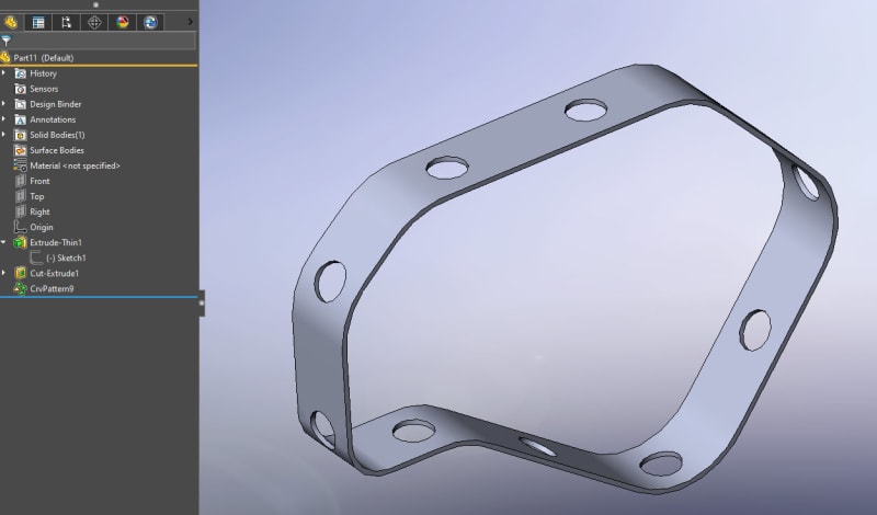
I'm trying to add some holes to a belt, but without succes.
I want to add the hole along the blue line (as seen in the screenshot).
Anyone got some ideas to do this?

I'm using Solidworks 2018.

Belt_mnf6ih.png
 
Replies continue below

Recommended for you

Have you tried to make your blue line one complete line, such as a composite curve, or maybe a fit spline to make it one continuous line without arcs\lines? Then it should follow and not stop at the arc\line intersection.

You can use the fit spline to make your belt one complete surface as well which might aid in what you are trying to do.

Scott Baugh, CSWP [pc2]
CAD Systems Manager
Dapco, INC

"If it's not broke, Don't fix it!"
faq731-376
 
If the belt is in a form such that you can flatten it, you can flatten it, put the holes in and then unflatten. See attached.
perf_wall_sample_vps4vc.jpg
 
perfbelt_aqjqff.jpg


> insert > sheet metal >

Swept flg - single line for profile, sweep path is belt path w/ small break, profile begins at break endpoint

Unfold- fixed face has endpoint on it for convenience, collect all bends

hole is just ext cut
linear pattern, edge for direction, specify pitch

insert > sheet metal > fold - same fixed face, collect all bends

all done.
 
Hello,

Thanks for the replies.
I wanted to avoid using sheetmetal if possible, But I don't think there is an easy way of doing this.
So I will try this method.
 
If it's just to show that the belt has a perf pattern in the drawing, I just do a partial perf, not to scale to show it in the drawing. Like that filter wall up above, if I did perf of the whole sheet, actual size, it would suck to work with and just look like a black or grey mess in the drawing. I show a partial pattern and note it to say what the actual hole size and spacing is.

You could just do a hole pattern in whatever area you'll show in the drawing to call out the belt. Just like modelling threads, you can take it too far.
 
Hi, S-eng:

You can add holes anywhere you want using HoleWizard command as long as you know where to add.

Best regards,

Alex
 
Hi, Scott:

I don't see a need to add a complete line or fit spline. OP just needs to pick HoleWizard command and place holes on the belt and along the blue line which does not have to be a complete line.

Best regards,

Alex
 
^, So to be clear, does the hole pattern follow the a line around the belt? I was unaware it would do that. Edit: that's right holes in thin parts will follow a local normal IIRC.
 
Hi, S-eng:

Sheet metal approach suggested by moon161 is a good approach. If you don't like it, you can try to use "Curve driven pattern" with HoleWizard command.

Best regards,

Alex
 
Hi all,

Thanks for the suggestions, I have used the Sheet metal approach.
Which worked good[thumbsup].
 
Status
Not open for further replies.

Part and Inventory Search

Sponsor