Eng-Tips is the largest engineering community on the Internet

Intelligent Work Forums for Engineering Professionals

Hollow Architectural Wood Columns

Status
Not open for further replies.

BS2

Structural
Feb 10, 2012
65
0
0
US
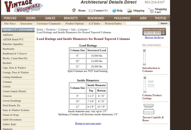
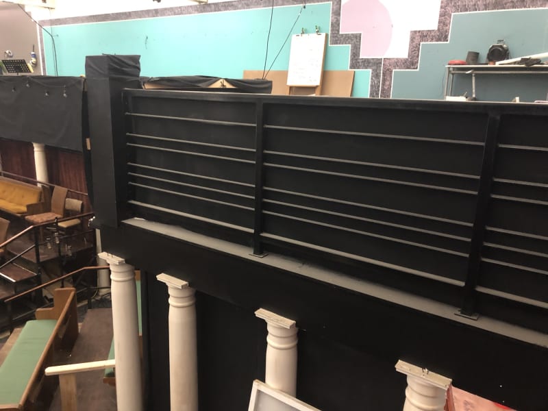
I have come across existing architectural wood columns which are hollow and tapered slightly. They are approximately 9" in diameter and consist of 12 individual "studs" glued together. How would I go about verifying the load bearing capacity? I was thinking that it could be approximated by four 2x4's in a square arrangement that each brace each other.

The required loading is approximately 4,200 lbs and the columns are approximately 9' tall. There is a column base and capitol which I would add blocking to in order to evenly distribute the load. Any help you are able to give would be appreciated!
 
Replies continue below

Recommended for you

If the studs are glued together, can they individually buckle? Or is a one for all an all for one situation. I assume they are 2x4s although you did not say that. If they are 2x4s, they should be able to easily handle that load if they cannot buckle and the load is somewhat evenly distributed. Without calculations I would assume 6 or less would hold that load.
 
I would not consider 4-2x4's as an equivalent approximation, as it bears no resemblance to the actual configuration in size or shape.

I also would not consider the glue to be an effective means to create a composite section. I would calculate the capacity of a single "stud" laterally braced by the adjacent "stud" and multiply by 9.

If that capacity was not sufficient, I'd hide an actual structural column inside of the architectural column (if possible).
 
12 x 1.5" = 18" >> 9". So I'm guessing that this is a faux circular column made of 2x glued on the flat with all pieces tapered in cross section and ripped where the column itself tapers?

The capacity of these columns will depend heavily upon how much you trust that glue and it's bond to the tapered wood in tension. Otherwise, the pieces will splay out like the staves of a crushed wine casket.

4200 lbs is nearly the curb weight of two Toyota Corollas. Do you feel confident you could park a pair of Corollas on these things? I've no doubt that they're plenty sturdy so long as the in individual "fibers" act as a whole.

Makes me miss my own mullet.

c01_dfvtjt.jpg
 
I second KootK's second question. Also, if it's a manufactured product, then the manufacturer should have load tables. If no load tables (which would indicate some level of testing), then I would personally assume zero capacity (which matches the level of responsibility I would take for someone else's product).

At the end of the day, I would see if there's already a real column inside of it. If not, get one in there.

Or see if the client has any stomach for load testing.

*sniff sniff* Kinda smells like a master's thesis lurking about. Going to guess your fee won't cover Load Testing and Analysis of Hollow Architectural Built-Up Wood Columns.
 
Instead of making a science project out of the glue, couldn't you just wrap it with some steel banding to provide bracing? Shoot some screws or lag bolts through the banding to brace each 2x4 either direction? Make it stainless so it looks nice.
 
BS2,
Are these columns you found and want to use, or are these already in use somewhere? If you found them and want to use them, then can you put a column in the middle as noted. Your original post sounded like they were made of 2x4s since you were trying to model them with a simpler arrangement of 2x4s. I found the following on the internet and I am submitting this as an example only. As someone already stated, the magnitudes may have been arrived at by testing. I am assuming the magnitude is based on Cd = 1. I do not know of a prescribed method to analyze one of these, I am sure there are reasonable methods to employ. But if you just only have 2 of these you need, a column inside may be cheaper than the possible mathematical gymnastics you will possibly have to employ.

Untitled_z7zb6m.png
 
On my previous post, I failed to note this supplier never cites a length of these proposed loads. That was one of the main things I wanted to point out and failed to do so. Also, of the old building columns I have had to look at, about 70% had an interior solid wood post when they were 2 story posts and had a somewhat slender appearance.
 
I have attached some pictures which show the column in greater detail. I have also attached a quick sketch of the column. When I mentioned tapered, they are tapered by approximately 1" over the length of the column. I believe that the individual pieces are relatively straight.

I am 100% positive that there is no post inside because I was able to see inside the column. The beams are bearing on the column capitol. This is for a mezzanine or balcony area and the work has already been completed. I am coming in after the fact and we will add columns if needed but I don't want to make them do this if it is not necessary. There are many posts and it would add quite a bit of work to go back and add all of these new columns.
 
 https://files.engineering.com/getfile.aspx?folder=109d9ec9-03e6-44e2-a7e2-85ca6ab43acc&file=Hollow_Round_Column_Sketch.pdf
BS2 said:
I am 100% positive that there is no post inside because I was able to see inside the column.
I guess the obvious question is, were the pieces separating at the joints allowing you to see in? Or did you somehow gain visual access to the top or bottom of the column?

At any rate, if it is actually as pretty as your cad drawing, then someone made this thing. You should find out who, and if they have any load tables. You should also make sure that it was fabricated with exterior exposures in mind. Short of that, I wouldn't try to analyze it - there's a bunch assumptions that you may not be able to verify. I would try and load up the column to 6,300 pounds or so (1.5 times your listed load). It still leaves the question of exterior exposure worthiness, but at least you'll have verified capacity.

Edited because I thought this was supporting a deck outside, and that proved incorrect.
 
The glue integrity is still your issue. A single 1.5x2.5 stud has no allowable at 9' without a brace. Column slenderness gets you. With a brace at midpoint, the load probably gets around 700 lbs per stud. Load testing as proposed shows integrity now but no guarantee in the future. How old do you think the columns are? It would be logical at least to use the age and current condition as a guide.

As KootK pointed out in his picture, your column more closely fits that profile so you have minor axis buckling outward and the glue is your only savior. Can you talk them into running a metal band around the column at mid-depth to insure no buckling at mid-depth similar to the barrel in the picture? The end joint details need to be worked out, but you could make it a decoration.

Another possibility is to make a sleeve that would fit inside. It only needs to go to the approximate middle. Fasten through the existing column into your sleeve that you can trust the integrity of.
 
I talk a good game when it's not my client relationship on the line. So I'll switch gears here and head into WWKD territory (What Would KootK Do). I'd pitch the load testing and be satisfied with that. Based on the similar product information that Ron provided, your odds of a successful outcome seem high. Then, if things go south, at least you've done something reasonable to assess capacity. My money says opposing counsel wouldn't be clever enough to think of the time dependent glue deterioration.

Thanks for the photos and sketches, that helps. Looking at the close spacing of the columns, I'm surprised at the loads they're drawing. Are some just architectural and not picking up any real load?

c01_rtnumd.jpg
 
I would also pursue the load test angle. I think it is reasonable, given that these are proprietary manufactured products for which you do not have complete knowledge of the materials and material properties (especially the glue) to evaluate them by analysis.

For what it is worth, I bet if you wanted to get all academic you could analyze these things and come up with a theoretical approximation of the tension forces across the glued interfaces, and I bet it is not all that large of a force, assuming the tension force between the glued pieces might be related to the required bracing force for a compression member.
 
Any decent glue is much stronger than wood in the cross-grain direction. Wood degrades too. If there is no apparent problem with the adhesive threat the column as if it were made from solid wood and made hollow. Laminated wood is stronger than solid wood.
 
Compositepro said:
Any decent glue is much stronger than wood in the cross-grain direction. Wood degrades too. If there is no apparent problem with the adhesive threat the column as if it were made from solid wood and made hollow. Laminated wood is stronger than solid wood.

In theory maybe, but I would not be comfortable relying on such an assumption for a composite wood product of unknown history, origin, quality, etc.
 
The columns are spaced a maximum of 6' apart and some are 3'-4'. I analyzed the beam as light storage as this is a theater and they are currently using it to store some light equipment, supplies, and performance equipment. They may turn it into a seating area and 100 psf would be more appropriate.

I have no problem believing they will hold 4,200 lbs or more. It seems entirely reasonable if they were new, of known origin, and were properly glued. I just wanted to explore if there was a reasonable way to analyze these as existing. Thank you all for the help.
 
Status
Not open for further replies.
Back
Top