Eng-Tips is the largest engineering community on the Internet

Intelligent Work Forums for Engineering Professionals

  • Congratulations waross on being selected by the Tek-Tips community for having the most helpful posts in the forums last week. Way to Go!

Hollow Jet Valve discharge

Status
Not open for further replies.

Hello everybody:

In the dam of a hydroelectric plant there is a pipe to discharge the ecological flow. See Figure 1. The entrance to that pipe is at an elevation of 270 meters above sea level (masl). The maximum water level in the reservoir is 290 masl and the minimum water level is 280 masl. The pipe has a diameter of 0,80 m and a total length of 40 m.

A few days ago, the reservoir reached its maximum level and the operation of the valve was tested. The flowmeter associated with this pipe registered a reading of 4,5 m3/s.

The Contractor argued that the flowmeter was giving an erroneous reading, given that the flow to be discharged with that maximum head should be 8 m3/s.

Over time, the level in the reservoir dropped and, for now, it is not possible to verify the situation: if it is the flowmeter that gives the error or that the pipe does not actually evacuate the 8 m3/s.

According to hollow jet valve discharge tables, with the dimensions at stake: reservoir head and pipe diameter, it is possible to evacuate 8 m3/s.

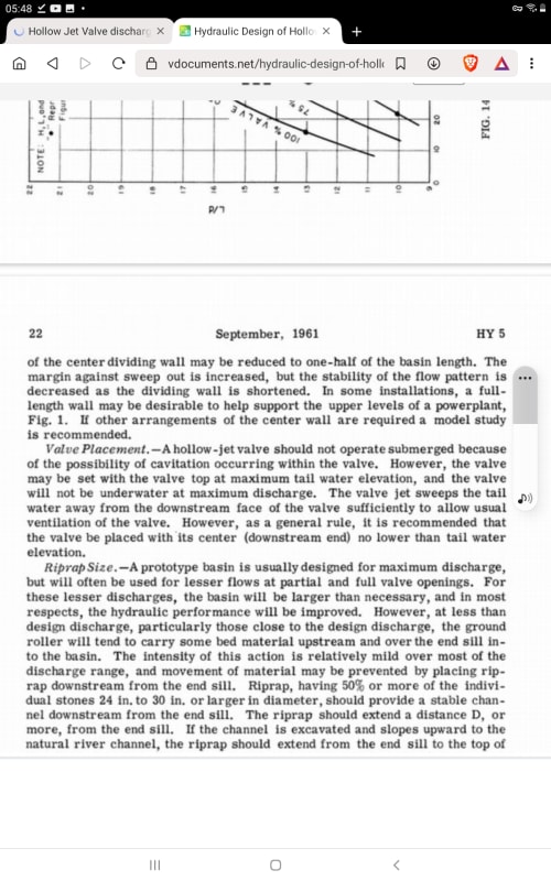
But, in the technical literature on these valves, as shown in Figure 2, when the valve is connected to an outlet pipe, the length of this pipe must NOT be greater than 4 times the diameter of the valve.

Here the question arises, can the length of the outlet pipe be the cause of the flowmeter reading?

Can the value of 8 m3/s actually be delivered or not by the valve/pipe?

Thank you in advance for your comments on this query.

El que no puede andar, se sienta.
 
 https://files.engineering.com/getfile.aspx?folder=0de5faf4-3bf5-40f9-9487-045728d4a28e&file=Caudal_Ecológico_-_EngTips.pdf
This doc says that hollow jet valves must not be placed in a submerged condition to avoid cavitation. Cavitation in your valve would limit or reduce flow.
Screenshot_20220820-054808_Brave_a6gfo8.jpg


A high backpressure on your valve is hydraulically similar to a submerged condition, so the length of pipe producing packpressure on your valve must be limited. Does your tail pipe configuration produce a backpressure greater than 4X D_valve? It looks like that's a yes, so according to the reference, cavitation is probably occurring and reducing your flow rate in the system.


Einstein gave the same test to students every year. When asked why he would do something like that, "Because the answers had changed."
 
In the pipe 8m3/sec is 16 m/sec.

That's very fast....

Remember - More details = better answers
Also: If you get a response it's polite to respond to it.
 
Hello everybody:

Thanks 1503-44, LittleInch and pierreick for your input. Let me tell you that, for the optimization of resources, we want to explore the idea of installing a small turbine to handle this ecological flow. For this, the hollow jet valve must be removed, leaving the butterfly valve as the inlet valve.

Initially, we think that it may be a cross-flow turbine (Michell Banki); but, we still do not know for sure the amount of water that we can dispose of. As standard velocity values for penstock 4 m/s to 5 m/s are used; which, in our case, for a pipe diameter of 0.80 m, by the Continuity Equation we have that the flow that could reach the turbine would be 2 m3/s.

What keeps squeezing my head is knowing, at least closely, how much the outlet flow is reduced by the back pressure imposed on the hollow jet valve by being connected to an outlet pipe. This, comparing it with a discharge to the free atmosphere.

Thanks again.


El que no puede andar, se sienta.
 
2112... I don't think any one really knows as you are using this valve in a location where it is not able to do the job it is intended for - release of large volumes in a controlled manner with the energy taken up by dispersing the water in a cone shape.

The velocity you mention is more normal for longer penstocks where you are trying to reduce the frictional losses to something reasonable so that most of the potential energy in the water is available for your turbines. in your case the head loss is quite small even at higher flows as there is only a short pipe, so you could have more flow.

If this valve is actually only used occasionally when the dam is getting close to overflowing, then I seriously doubt the expense of a turbine will be recovered in energy.

first get your design worked out.

So what is the max flow you need from this pipe, which looks to me like it is a release valve / water level control to stop uncontrolled over topping. So if someone thought you needed 8m3/sec to prevent this, then you can't just suddenly restrict it to 2m3/sec

You will need some way of controlling flow into the turbines, but I guess the turbines come with their own control system?

I don't know enough about the differences between water turbine types and power rating etc but with only 20-30m head, you're into a relatively low head machine.

Remember - More details = better answers
Also: If you get a response it's polite to respond to it.
 
Hello everybody:

Thank you LittleInch for your input.

Originally, the designer thought that the 8 m3/s could be released through that pipe. In the location where the valve was installed, which is not the appropriate one, the 8 m3/s CANNOT be discharged through the pipe.

But some people in my office say: "... well, with 8 m3/s and the available head it can be generated xxx kW..."

This is where I tell them, “Forget about 8 m3/s discharge, the most you can have available for power generation is 2.0 m3/s." Even so, they insist that the 8 m3/s can be made available "because that is how the designer established it".

As a typical value for water velocity in a penstock, 4 m/s is taken, which has been, and is, widely accepted by almost all turbine designers. With this velocity value, in our case, with a diameter of 0.80 m and by the Equation of Continuity, Q = V*A, the flow rate that any turbine can handle is 2.01 m3/s.

With this flow flowing through the pipe, total losses are generated, according to Darcy Weisbach, of 2.57 m. From Fig. 1, the gross head is 290.0 - 261.0 = 29 m. Subtracting the losses, we have a net head of 26.43 m. That net head with a Michell Banki turbine with an efficiency of 82%, would deliver a power of 427.34 kW.

Thanks again.


El que no puede andar, se sienta.
 
Just make the pipe that goes into the turbine a bit bigger to reduce the velocity surely, or split it into two?

If you're going to go power generation, then you need to remove the hollow jet valve or bypass it.

your issue seems to be what is a flowrate that can flow for a large percent of the time (>50% of the year).

Anything less and it will cost you more to install all the equipment and electrical system than you'll make back in power, though with current power prices, that might decrease a bit. But is going to be >30% of the time minimum.

Unless you can uses this mysterious water supply as pumped storage?

Remember - More details = better answers
Also: If you get a response it's polite to respond to it.
 

21121956,

How did you calculate the pressure loss with the Darcy-Weishbach equation without having a flow rate?
With gravity flow you start with a first value guess for the flow rate and then you iterate the calculation process with the darcy-Weiesbach equation until the pressure drop matches the deltaH available.
 
Hello everybody:

Hi Ione1, as I indicated in my last comment, accepting a velocity of 4 m/s and with the pipe having a diameter of 0,80 m, the typical flow rate that any turbine would handle would be 2 m3/s.

With this flow circulating in the 40 m long pipe, having eliminated the hollow jet valve and leaving the butterfly valve in place, the total losses according to Darcy Weisbach are 2,57 m. This is how I calculated the losses.

Thank you all.

El que no puede andar, se sienta.
 
I have a different interpretation why your flow is lower than expected.
The hollow jet valve needs to be ventilated with ambient air to fill the conical void downstream of the valve. With higher back pressure than the valves intended application the ventilating air will be lower to non existent. The following may occur, both will have negative impact on the valve and discharge pipe service life.
[ul]
[li]Two phase high velocity flow in the discharge pipe. Pressure loss will be much higher in this pipe than single phase flow calculations show.[/li]
[li]Two Phase flow water hammer (slugging).[/li]
[li]Less than design damping of cavitation, possibly causing erosion at or near the valve.[/li]
[/ul]
Inspecting the valve and pipe for erosion after a period of usage is recommended.

If it is possible to move the valve to the downstream end of the pipe, the pipe and valve may flow much closer to the intended design. If you decide to install a water turbine, you still need an emergency discharge valve.

How much of this missing flow is needed to flow your design flood?
 
Hello everybody:

Hi FacEngrPE, as I indicated in my first post, having the maximum level in the reservoir, the valve was fully opened and a flowmeter showed 4,5 m3/s, a value far from the 8 m3/s proclaimed by the Contractor.

Thanks for your input.

El que no puede andar, se sienta.
 
The contractors stated maximum flow value might or might not be the Maximum Probable Flood. If the flow achieved is higher than the Maximum Probable Flood, it might be possible to accept the condition. If the achieved flow does not achieve Maximum Probable Flood, you now have information that will require a solution.

Your project should have documentation explaining how the Maximum Probable Flood was determined, and it's value.

Link to some examples of Probable Maximum Flood Estimation

 
Status
Not open for further replies.
Back
Top