Continue to Site

Eng-Tips is the largest engineering community on the Internet

Intelligent Work Forums for Engineering Professionals

  • Congratulations SSS148 on being selected by the Eng-Tips community for having the most helpful posts in the forums last week. Way to Go!

Horiz. Joist Brdg. Failure 1

Status
Not open for further replies.

EngStuff

Structural
Jul 1, 2019
81
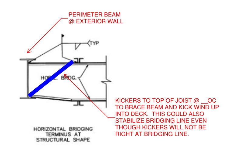
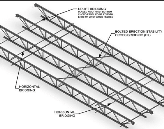
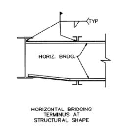
One thing I don't understand and need a little input. When we have a steel building with end beams being W-shape but interior beams being Web Joists (see vulcraft pic below). When I see this type of bridging shown below. I get a little confused about something. To break my question into 2 parts. Q1 gravity with no uplift. Q2 uplift included.

Q1. Assuming it's a floor with gravity load only. The bottom horiz. bridging is in tension in this case. but can't the bottom flanges of all joists and the end W-shape beams fail by twisting together in one direction?

Q2. Assuming it's a roof with uplift load only. The bottom horiz. bridging is now in compression in this case. Same as above, can't the bottom flanges of all joists and the end W-shape beams fail by twisting together in one direction?

Don't we need to have X bridging at the end? or is there a reason why we don't use x bridging at the ends when we have W-shape beams as end beams? Thanks.

joist_bridging_mlhlxf.jpg
 
Replies continue below

Recommended for you

For both cases, the top and bottom bridging are pressed by chords, that resulted in tension. The top and bottom bridging are liking two catenaries.
 
1) Rightly or wrongly, the bridging is assumed to be unaffected by the vertical displacement of the joists.

2) Unless the beam bottom flange is laterally restrained somehow, I would not expect the bridging emanating from it to stabilize the bridging line. Rather, you'd want a diagonal or two kicking up to the roof deck or attachment to a block wall etc.

 
r13, thanks! I see what you mean by that. That makes sense.

KootK
1. For the 2nd floor gravity floor loads. Do we need to make sure that the W-shape beams at the ends are able to resist the force from the bridging at the bottom flange? since SJI calls out the maximum bridging force on table 2.7-2? I'm afraid of if there is no x bridging at the ends, that the forces might cause the bottom flange to push/pull horizontally.

2. That's what I ended up doing for the roof. I was not too comfortable with it being horizontal only.
 
OP said:
Do we need to make sure that the W-shape beams at the ends are able to resist the force from the bridging at the bottom flange?

I would think so, yes. With respect to the detail that you posted, are you sure that isn't about the bridging bracing the bottom chord of the beam rather than the bottom chord of the beam stabilizing the bridging?
 
KootK,

To be honest, I have no idea. I saw it on the vulcraft catalog. That the bridging of the joists need to be anchored at the wall (if exists) or W-Shape beam. In my case, I have a W-shape beam. So my assumption was that the detail was for bottom chord of the beam to stabilize the bridging. In my case, I did not design the beam bottom chord to stabilize the bridging.
 
EngStuff said:
So my assumption was that the detail was for bottom chord of the beam to stabilize the bridging.

And your assumption may well be correct. See one common example below in which it would be. I feel that the key here is simply to recognize, as you have, that the bridging imposes a lateral demand that must be resisted somewhere.

C01_xp2j3d.jpg
 
KootK,

What you drew makes more sense. I will detail that diagonal in there. Thank you very much! I appreciate the help!
 
You're most welcome EngStuff. 'Twas a learning experience for me as well thinking through it.
 

Just a personal quirk (and, I've got lots of these) for short span joists I put x-bridging in each 100' and for long span every 60' as well as x-bridging at the ends...

Rather than think climate change and the corona virus as science, think of it as the wrath of God. Feel any better?

-Dik
 
Based on my limit experience, the joist providers do provide transverse cross bridging or diagonal bridging, but I believe it is by order from the purchaser, or the EOR (check me on this). The cross bridging and diagonal bridging are usually placed in the interior panel joint at a specified spacing (again check it). What KootK and Dik described is "joist end/end bay bracing" by design.

image_os14nn.png
 
@dik and r13. Thanks guys I appreciate the info!
 
Status
Not open for further replies.

Part and Inventory Search

Sponsor