Eng-Tips is the largest engineering community on the Internet

Intelligent Work Forums for Engineering Professionals

Horizontal Stiffener to increase beam shear capacity

EngDM

Structural
Aug 10, 2021
367
1
16
CA
I'm referencing CSA S16:14 and I'm seeing that for Cl. 13.4.1.1 if you have a stiffened web you have different requirements. Firstly, is it referring to transverse vertical stiffeners or a horizontal stiffener? I've seen horizontal stiffeners used for web buckling but I have not myself specified it.

Is there a CSA reference example that one of y'all may have that would go horizontal stiffeners?
 
Replies continue below

Recommended for you

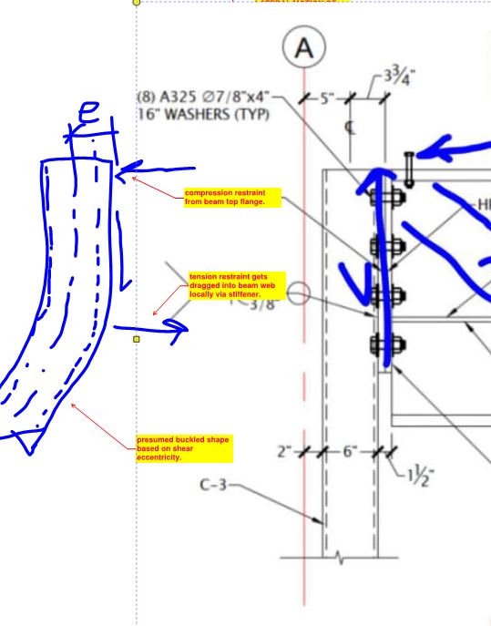
Unless I'm missing something significant, a gravity load on the beam would produce a clockwise rotation at the end of the beam. The restraint by the column, small though it is, would produce tension in the top of the beam and compression in the web, concentrated toward the bottom of the end plate, wouldn't it? In that case, the stiffener is right where it would need to be in order to prevent buckling of the web due to the horizontal compression.

I'd be very surprised if the column can generate enough restraint moment to produce compression substantial enough to require a stiffener to prevent buckling of the that fairly stout web, though.
 
why would they make such a butt ugly joint in the first place ? why not a full depth joint ?
Maybe they had a shallower beam initially, then increased the beam size (for mid span moment), and some bright spark said we don't need the extra strength at the ends so retain the previous joint plate ... ?

"Wir hoffen, dass dieses Mal alles gut gehen wird!"
General Paulus, Nov 1942, outside Stalingrad after the launch of Operation Uranus.
 
rb1957 said:
why would they make such a butt ugly joint in the first place ? why not a full depth joint ?

It's quite common to do end plate connections that are not full depth. I think that the spirit of it is to prevent direct contact between the compression flange and the supporting thing in an effort to limit the amount of moment transfer at the connection.
 
Does no one think this could be to strengthen the connection for an axial load. We've got a nailer on the top of the beam. Couldn't this be a drag strut, compression chord or part of a flexible diaphragm anchorage or something?

I'm just looking at the combination of the eight 7/8" bolts, the slenderness of the column, and the stiffener. It feels like this could be there to strengthen this connection for an AXIAL load.
 
JoshPlumSE said:
Does no one think this could be to strengthen the connection for an axial load.

I have considered that. I just don't feel that it's the most plausible explanation based on the information that we have so for.

When I look at this detail and imagine it being for axial load transfer, the first question that pops into my head is "axial transfer to where??". To some brace that just isn't shown in the detail for some reason? To the column acting as a very sad moment frame column?

In a way my explanation below also speaks to axial load: the axial compression arising from flexure.

KootK said:
Then my vote is that the stiffeners were detailed to deal with inadvertent flexural compression in the bottom of the connection.

Fundamentally, I feel that using a short, horizontal stiffener is a foolish way to try to improve shear capacity. Which, in part, is why I doubt that it was detailed to improve shear capacity.

The 7/8" bolts confuse me. My best guess there is that this details is a fabricator's detail and the the large bolts are a result of some silly general note someplace on the EOR drawings. Maybe a requirement to design the connection for Vf = 50% beam web shear capacity etc.


If this were some sort of drag connection dumping a bunch of axial load through the bolts into the column and then to ..somewhere, the horizontal "stiffener" could just be a means to achieve more weld length to the beam web, or rather, engage more of the beam web. As if ~30" of 1/2" fillet weld isn't enough. But then again, the web is only 3/4" thick. Although the already-confusing and seemingly incorrect weld symbols don't indicate that the stiffener is welded to the end plate.

I don't see how this would increase the vertical shear capacity of the connection other than just trying to keep the web from pulling away from the end plate. I.e., utilizing the "stiffener" to resolve horizontal component while utilizing the web-to-endplate weld for vertical, direct shear only. Maybe they checked that weld as an eccentrically loaded weld and figured it wasn't enough.
 
KootK said:
When I look at this detail and imagine it being for axial load transfer, the first question that pops into my head is "axial transfer to where??". To some brace that just isn't shown in the detail for some reason? To the column acting as a very sad moment frame column?

I thought the same thing. But, we don't exactly have a full set of drawings. I assumed that there's something we're not seeing. Another thing I though was interesting is that this spindly little column is offset from grid line A. I'm thinking that grid line might be a partition wall, cladding or something. Something this could be attached to the column by girts or something that run perpendicular to our view, but which are not directly associated with this connection.
 
I guess the other thing that informs my thinking on this is OP's location: Manitoba, Canada. His building probably doesn't even have a designated lateral system, yet alone one with gignormous drag struts flying around. I can say catty stuff like that because it's the same for me over here in AB.
 
Comedy, but realistic, option. One engineer sketched up an end plate not connected to the bottom flange to avoid moment transfer, and then another engineer reviewed the shop drawings and didn't like the lack of restraint and added a stiffener to create fixity.
 
JoshPlumSE said:
Couldn't this be a drag strut, compression chord or part of a flexible diaphragm anchorage or something?

Ding ding ding, the walls above are shearwalls it seems. However, with the whole main floor being steel framed and not a single moment connection is identified, and no X braces are provided in the main floor, I don't really see where the lateral load is actually going... Unless they sized these connections as moment connections and just didn't provide loads? Not really typical to see that where I practice; connection design is delegated to the supplier and loads are shown on the drawings.

The intermediate (not at end of beams) don't appear to be moment connections either, simply a beam bearing on HSS column detail was provided with small welds and 4 bolts.
 
KootK said:
I guess the other thing that informs my thinking on this is OP's location: Manitoba, Canada. His building probably doesn't even have a designated lateral system, yet alone one with gignormous drag struts flying around.

Yea what is a "designated lateral system" heh.
 
Making some assumptions here but I feel that a pretty good story would be:

1) Shear walls transfer at beam so lots of OT shear and need for stiffness at the beam.

2) Drag load thought to be transferred into diaphragm at the beam level and resolved someplace else. Maybe a stair or elevator shaft.

3) Column is architecturally constrained to its small dimensions.

4) For the high loads, steer clear of beam over column (roll over) and shear tab (eccentricity).

5) Choose this end plate setup to minimize eccentricity of shear delivery as well as provide moment restraint to the column.

6) Kind of get confused as to whether or not you want this to be a moment connection.
 
Like this. I have more sympathy for it now. In fact, I retract anything that I previously said that would question the skill of the designer. I see skill here now where previously I thought that I saw folly.

c01_oq48tn.jpg
 
Looks like this thread has narrowed it down to a more likely intent.

KootK said:
You'll have to hold my hand a bit here. How does "any flange" improve shear capacity?
In typical sections/loading flanges aren't really contributing to vertical shear capacity, that was my unhelpful way of stating it.

KootK said:
6) Kind of get confused as to whether or not you want this to be a moment connection.

Seems like it must be a moment connection for the column whether the beam wants a moment connection or not, and I'm not personally aware of any methods that produce a one-way moment connection (ratcheting mechanisms?) . Still don't quite like the fact the connection doesn't extend to the bottom flange.

I do have a thought that I'm not quite confident in, but I don't think that sketch (or rather, the logic behind using the beam to restrain the column) reflects reality when we consider the beam's moment. Negative moment at the end of the beam (I assume there must be some that can't be neglected, if it's a moment connection in order to "restrain" the column) would be acting in tension top / compression bottom and rotate the column further in the undesirable direction rather than what is being intended.

----------------------------------------------------------------------

Why yes, I do in fact have no idea what I'm talking about
 
dold said:
OP, is there any chance we can have a look at the framing plan where this section was cut?

I'm not sure I can provide this, however if you describe what additional info you are looking for I can try to describe it.

Basically, it's a main floor beam holding OWWJ from either side, and connection occuring in the exterior wall (end of the beam line). Has a shearwall above it (no holdowns, likely no tension).
 
Then I really don't buy the axial load argument if this is the end connection at the main floor level. There's a column at the exterior end of a beam below the main floor? Seems odd.
 
jayrod12 said:
There's a column at the exterior end of a beam below the main floor? Seems odd.

I'm not sure what you mean by this. How is having a beam supported within the wall assembly via HSS column odd?
 
Back
Top