Continue to Site

Eng-Tips is the largest engineering community on the Internet

Intelligent Work Forums for Engineering Professionals

  • Congratulations KootK on being selected by the Eng-Tips community for having the most helpful posts in the forums last week. Way to Go!

Hot Water & Heat Recovery Design 1

Status
Not open for further replies.

ISSAM_20

Mechanical
Mar 21, 2020
4
Hi Everyone,

I'm working on a hot water plant design but the client instructed us to associate this design with a heat recovery system which is available due to compressor helium cooling.

So we did as asked and we link two hydraulic loops directly on the cold line of the main loop, as show in the drawing below.
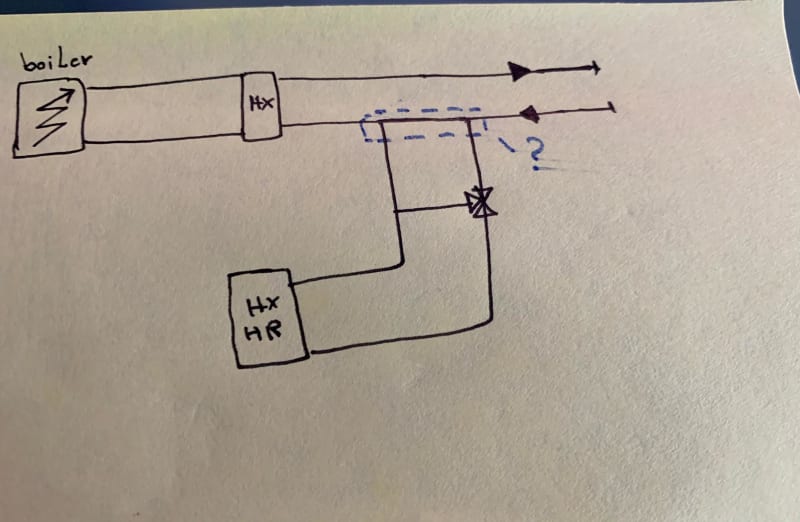
Drawing_ed7hc9.jpg


my concern now and after reading little bit about it, is the Hydraulic separartion of those two loops as i did not forseen any Hydraulic separator ( switch) on the design.

The cuurent layout i have is that the two brahces which goes to the Helium compressor exchanger are only 800 mm far from each other ( see screen shot from 3D below).
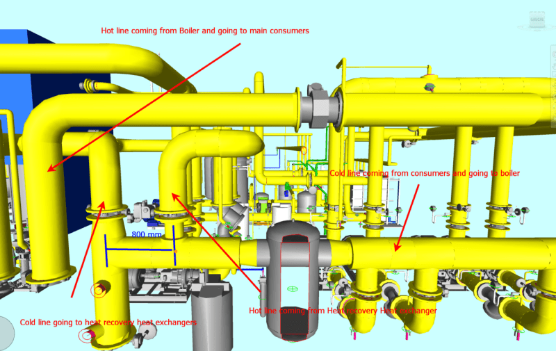
cap1_npm61a.png


Do you think that this arrangement will have no issue to manage the hydraulic separation betwen the two loops?

Thank you in advance for your help.
 
Replies continue below

Recommended for you

To ensure hydraulic separation keep the distance between the inlet/outlet tees not more than 2 to 3 pipe diameters. The purpose is to have as small a pressure drop possible to prevent the flow in one loop affecting the other. see more here

Is there a seperate pump for the heat recovery loop that is not shown on the schematic?

What is the purpose of the 3-way valve? Temperature control? If your pump has a VFD, you can just eliminate that valve.

 
Hi Immsk,

Thank you very much for your feedback.

I agree that the purpose is to have a minimum pressure drop betwen the two TEEs, But i think this is true if only we have a straight pipe before TEEs with a a considerable Length, don't you think?

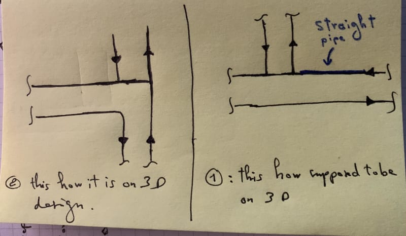
But according to the pipe layout shown above, i dont have a straight length, the Main return line is directly connected to the inlet branch going to Heat Recovery ( see the schematic below).

Schem2_hafjme.jpg


To answer to your questions :

Yes i have a separate pump on the heat recovery with a VFD included.

The 3 Way valve, is to ensure the right temperature in the main loop, i have 85°C maximum, but the temperature from Heat recovery could reach 120 °C. it should be amixing on the other line not a diverting.

Thanks
 
On schematic 2, are you able to show the pumps and label the equipment to which flow is going to and coming from?

Instead of the 3-way valve, you can just have the VFD ramp up/down to maintain 85c in the building loop.
 
It looks like you are on the suction side of your main pumps and right next to the air seperator and (I would assume) expansion tank. I don't see a significant problem with your 800mm separation or the fact that one line is on a tee. I don't see a significant pressure drop across that 800mm piece of pipe.

I assume there is an alternate means to cool the HE Compressors? The amount of heat you recover from this system seems like it could vary and not be a dependable means to cool the compressor.
 
If your main system pump is larger (flow/head) than the HX pump, then it should work. The small pump cannot overcome the larger pump in the decoupler.
I have seen such an arrangement with the decoupler barely 12" long and it worked.
 
Status
Not open for further replies.

Part and Inventory Search

Sponsor