Continue to Site

Eng-Tips is the largest engineering community on the Internet

Intelligent Work Forums for Engineering Professionals

  • Congratulations KootK on being selected by the Eng-Tips community for having the most helpful posts in the forums last week. Way to Go!

Hot Water Circulation Pump.

Status
Not open for further replies.

S.G

Petroleum
Dec 22, 2022
63
Dear Team,
Please find the attached datasheet for a hot water circulation pump.
We have experienced failures and loss of metal in the impeller, as well as in the first 5 inches of the discharge piping.
The operating conditions are as follows:
• Suction pressure: 1.2 barg
• Discharge pressure: 4.9 barg
• Temperature of fluid: 100°C
• Flow rate: 180 m³/hr to 200 m³/hr
Could you please confirm whether we are operating the pump outside its recommended operating envelope?
 
 https://files.engineering.com/getfile.aspx?folder=81eaacee-a49a-46c3-9e33-55acf04a5b94&file=4c83b2ba-334c-420e-8236-ee54d71ea614.jpeg
Replies continue below

Recommended for you

HI,
LI your comment about vapor pressure is not correct.
Vapor Pressure is expressed in absolute, and its value is about 1 bar @ 100 c
NPSH a is about 10.33 Meter of water without taking account dissolved gas.
I've attached another document on the subject.
Pierre
 
Vapor pressure of water at 140degC = 3.32bar abs = 36.8m head abs
So to keep an NPSH margin of say 2m to the min required of 7.3m at 180m3/hr, and assuming 1m head loss for friction in the 14inch suction line, min expansion drum N2 pressure should be = 36.8+7.3+2+1-1.4=45.7m of liq abs = 3.1barg at design case suction temp of 140degC.
 
Missing document
additional comment: If you calculate the suction specific speed you will get 9725, close to the upper limit (10000) (US units). High risk of cavitation.
BTW I'm quite surprised that the vendor is offering a pump with such RPM (3555) for this application (high temp fluid).
Good luck.
Pierre
 
 https://files.engineering.com/getfile.aspx?folder=7e16440e-dae8-4dff-85e6-e8b55f9b0640&file=dissolved_gas_in_liquid.pdf
@SG,@pierrick, Indeed, vap pressure at 100degC is 1.013bar abs. So, correcting my previous calc,

"In any case, if we assume actual suction line loss = 1.0m, then remaining head = 27.1-1 = 26.1m abs. Subtracting vapor pressure of hot water at 100degC,which is 1.013bar abs = 11.2m, then net head remaining at pump suction = 26.1-11.2=14.9m.
The pump datasheet states a minimum NPSHr of 7.3m at 180m3/hr, so you've got plenty of margin, if max operating feed temp is limited to 100degC."

I havent made a similar error in the calc for 140degC operating temp.

As noted previously, this arrangement with expansion drum sitting on a tee in to the main 14inch suction line doesnt help at all with vapor disengagement in the feedstream. So if you have a tube break in the HX, and HW press < crude pressure, crude vapor will get into HW return, and you will have cavitation in the pump, even if your pump suction temp is 100degC.


Dear George and Pierre,

If the vessel or tank on the suction side of the pump is under nitrogen blanketing or has an internal pressure different from atmospheric pressure, you do not add atmospheric pressure when calculating the NPSH available (NPSHa). Instead, you use the actual absolute pressure inside the vessel or tank.

In such cases, the pressure inside the vessel is already an absolute pressure, right?

Goerge, you added the atmospheric pressure. See below:

Suction pressure at pump if there were no frictional loss = 1.3 + (1.46*0.92/10.2)+1.013 = 2.44bar abs = 27.1m of head abs = 1.44barg
 
P.S. The pump operating pressure is 100 to 105 C.
Trip set point : 115 C
 
Hi,
To avoid mistakes, use absolute pressure only and convert gauge pressure and relative pressure to absolute pressure.
P abs=P gauge+ P atm =P relative + P atm
Pierre
 
Hello Pierre,
But, George added the P atm to the suction pressure.
It is a closed system, with N2.

If the vessel or tank on the suction side of the pump is under nitrogen blanketing or has an internal pressure different from atmospheric pressure, you do not add atmospheric pressure when calculating the NPSH available (NPSHa). Instead, you use the actual absolute pressure inside the vessel or tank.

 
@SG,
NPSH is based on absolute pressure, not guage. So guage pressure at the expansion drum should be converted to abs pressure for determination of NPSH.

If temp trip setting on the pump is 115degC, but pump datasheet says feedstream temp is 140degC ?

Think an inspection and hydrotest of the crude HX tube bundle is required.

 
Dear George,

The tube bundles were inspected and the 'leak tested' two weeks ago, and no issues were found.

Also, according to the pump datasheet, the pumping temperature range is 110–140°C. Our process requirement is less than 115°C.

The pressure control valve set point on the hot water expansion tank is 1.5 barg. We will be raising this to a minimum of 2.5 barg? Should we do this anyway?
 
As @LI pointed out earlier, your pump dp of 3.8bar = 41m of head, which, from the pump curve, indicates an end of curve operation with flow at over 270m3/hr and NPSHr at nearly 10m, which contradicts your stated flow of 180m3/hr. Can you explain?

BTW, is that a check valve I see on that 3inch exit line from the expansion drum ? If it is, it would impede reverse flow of any vapor in the 14inch suction line back into the drum? It should be removed or the internal plates should be removed. Line velocity even at 270m3/hr in the 14inch line is 0.8m/sec, so friction pressure drop should be low, and not a problem.

At 115degC, HW vap press = 1.8bar abs = 20m liq abs, so min required tank press = 20 + 10 + 2 + 1.0 - 1.4 = 31.6 m liq abs = 1.8barg even at end of curve operation, so 2.5barg is directionally better. But we still dont have an explanation for the damage done at these pumps, since you say suction temp was all this while less than 105degC at 180m3/hr, and there are no tube leaks at the HX, so I dont know if increasing this drum pressure is the solution. Are there any other heat exchangers with volatile fluids in this HW closed loop ?


Your other post ( this is why double posting is not allowed ) said your flow data comes from a meter on the output of the heater. So is this just divided by the number of pumps running?

There is no individual pump FIT I can see.

Looking at the P&Id, it looks like there could be a potential misbalance between pumps.

Not all pumps are equal.

Has this system now operated with more or fewer pumps than before?

How do you operate? All pumps or variable number. What controls flow?

But yes, set the N2 at min 2.5 barg.

Then you can eliminate cavitation as a damage mechanism. But there is something not right with flow or pressure differential.

Remember - More details = better answers
Also: If you get a response it's polite to respond to it.
 
Thank you all for your input.

Attached is the datasheet of the oxygen scavenger added. I noticed that the boiling point is 105°C; and for the water temperature in the system downstream, the hot water generator is 110°C; and the return fluid temperature to the water circulation pump is 100°C. See my thoughts below:

An oxygen scavenger with a boiling point of 105°C to a hot water system where the water temperature is above 105°C could potentially lead to issues, but whether it causes cavitation in the pump depends on several factors:

1. Vaporization of the Oxygen Scavenger: If the scavenger boils at 105°C and the system operates at a temperature higher than this, the scavenger might start to vaporize. This could lead to the formation of gas bubbles in the liquid.
2. Cavitation Risk: Cavitation in pumps occurs when gas bubbles form in the liquid and then collapse violently as they move into regions of higher pressure within the pump. This can happen if the scavenger vaporizes, creating gas bubbles.
3. System Pressure: The actual boiling point of a substance depends on the pressure. If the system is pressurized, the boiling point of the oxygen scavenger might be higher than its standard boiling point. This could prevent it from boiling and forming gas bubbles under operating conditions.
4. Pump NPSH Requirement: The Net Positive Suction Head (NPSH) required by the pump is a critical factor. If the NPSH available (NPSHa) is less than the NPSH required (NPSHr), cavitation is likely. The vaporization of the oxygen scavenger could reduce the NPSHa.
5. Chemical Interaction: The interaction between the oxygen scavenger and water, and how it affects the overall boiling point and vapor pressure of the mixture, should also be considered.

The pressure control valve set point on the hot water expansion tank should be set to a minimum of 2.5 barg. By doing so, we can effectively eliminate cavitation as a potential damage mechanism.

I will get back to you with more details tomorrow.
 
 https://files.engineering.com/getfile.aspx?folder=7b68157c-751f-4b17-b159-f4a7ffd248fb&file=NORUST_SC_47_Z_UAE_-_Oxygen_Scavenger.pdf
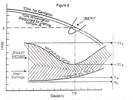
You also need to remember that NPSHR is NOT the cavitation limit.

This is at a higher pressure / head than the NPSH curve which is defined as the head vs flow where the differential pressure drops by more than 3% compared to no limit of inlet pressure. If you've ever gone to pump test, when they do NPSH you can often hear the cavitation start before they call the reading for the 3% differential head loss reading.

The usual margin is 1-3m , but at higher flows and higher pump speed this can increase to 5m or more above the NPSH curve..

This is one mf my favourite graphs. The bottom line is what your pump curve says. the top line is where cavitation starts.

I think your pumps are also not balanced so that one could be pumping a lot more than the other on or two (you haven't answered those questions yet).

NPSH_eqrc70.jpg


Remember - More details = better answers
Also: If you get a response it's polite to respond to it.
 
Hello LitteInch,

Please see below. Three pumps were running yesterday:

Hot water circulation pumps

Suction/discharge pressure:

P-A - 0.9 / 4.9 barg;
P-B - 1.0 / 5.0 barg;
P-C - 0.8 / 4.9 barg

Flow A - 173 m3/hr; B - 190 m3/hr ; C - 169 m3/hr.

Expansion tank level - 1,463 mm and pressure - 1.3 barg.
 
I'm curious as to how you're measuring flow - there was no FIT shown on the P&ID?
Temperature yesterday?

Those differential pressures all look very low compared to the pump curve.

Remember - More details = better answers
Also: If you get a response it's polite to respond to it.
 
Hi LittleInch,

We have three hot water generators, and we have a flow element downstream from each generator.

The temperatures yesterday:
Inlet temperature at the suction of the pumps (return line from the hot water generator): 101°C

Hot water generator outlet temperature: 111°C
 
If we can trust the NPSHr for these pumps, then I would suspect this damage is chemical corrosion, given there is adequate NPSH margin with expansion drum at 1.2barg.
Since you would be using demin or DI water in this circuit, it can be corrosive if you havent been keeping tabs on dissolved O2, pH in this closed loop, or if this bisulfite scavenger chemical is not compatible with the pH adjustment chemical (which is a mix of propyl amine and ethanolamine) you are using. If this chemical treatment is not yielding expected results on dissolved O2, then would suggest going for a higher alloy construction for these pumps.
Did your lab do an analysis of this HW stream prior to discovery of this failure ? What are findings?
 
Hi,
On top of mechanical issues (cavitation, erosion) you should call the company in charge of water treatment at your facility to perform tests on your water and asking them to confirm the quality of the treatment for hot water, in particular the location of the introduction of the O2 scavenger.
Regarding pumps you should issue a specification sheet and get proposals from reputable vendors, this will confirm the primary choice. I had good experience with KSB on hot water to heat up polymerization reactors.
Note: I'm quite suspicious about your gauges and head losses on the suction line. Considering your flowrate, with a Hypothetical pipe length of 10 m ,80 mm diameter, fitting Ki of 1 and data from the pump vendor (density, viscosity) I got a head loss of 1.5 bars (Darcy Weisbach equation).

Pierre
 
Dear George and Pierre,

Yes, the chemical injection commenced on August 14th. We have a lab analysis almost every three days. See the below readings from November 14th:

How water generators:
pH: 7.95
TDS (ppm): 2375
Chloride content (ppm): 160
Conductivity: 4754
Dissolved O2: 169

Expansion Water Tank:
pH: 7.9
TDS (ppm): 2172
Chloride content (ppm): 140
Conductivity: 4346
Dissolved O2 (ppb): >800
 
Status
Not open for further replies.

Part and Inventory Search

Sponsor