Continue to Site

Eng-Tips is the largest engineering community on the Internet

Intelligent Work Forums for Engineering Professionals

  • Congratulations waross on being selected by the Eng-Tips community for having the most helpful posts in the forums last week. Way to Go!

How best to add GD&T to ensure symmetry

Status
Not open for further replies.

RCor

Mechanical
Jul 26, 2023
4
Hi!

I'm trying to dimension and add GD&T to this cross-section
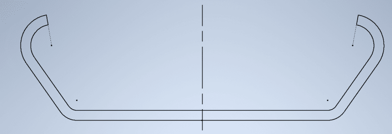
Profile_Normal_ppl3q1.png


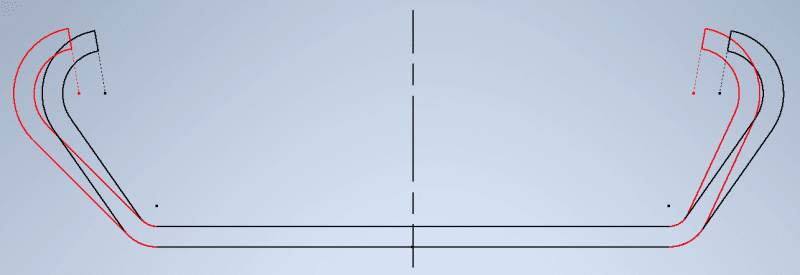
to prevent the left and right from going asymmetrical like this (over-exaggerated)
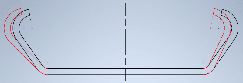
Profile_With_Asymmetry_tzhktd.png


I've tried several things (see below), but haven't found a good solution that is both correct and measurable by operators (with simple gauge(s) and or caliper).

(Note that I use the upmost dimension as reference since this is the dimension with the smallest tolerance on it)


Option 1 - makes no sense since centerline of referenced dimension moves along with centerline of reference
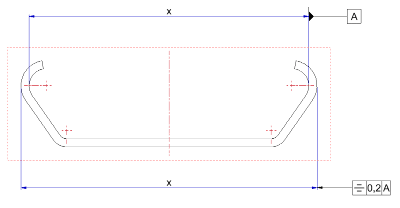
Symmetry_1_negkgr.png


Option 2 - would make more sense, but not sure how this would be measurable
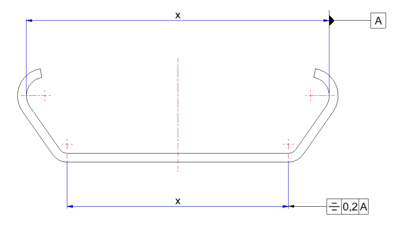
Symmetry_2_zwfwe8.png


Option 3 - basically like option 1: centerline and position move together
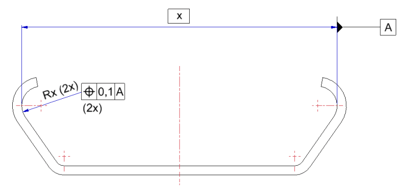
Positional_youyhu.png


Any tips or advice is very welcome!
Thank you in advance!
 
Replies continue below

Recommended for you

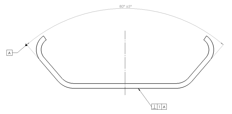
I'm more familiar with ISO GPS. I've attached a suggested way to do what you're asking below and I'm pretty sure this would be ok under the GPS standards. Maybe someone familiar with ASME could verify. Using the angular feature of size as a datum creates a datum consisting of the bisector plane between the two faces and axis where the faces would meet if they were extended. A perpendicular constraint can then be placed on this datum to constrain the horizontal face relative to the bisector plane. Depending on the part function you will still need to tolerance the other features, but how to do that would be hard to know without more context.

Capture2_j1mfqg.png


Ryan.
 
Thanks for replying, Ryan!

How would defining the perpendicularity of the bottom surface help in creating a symmetry of the angled surfaces?
Maybe I'm missing something or my initial question wasn't explained well enough?

Dimensioning and tolerancing the other features is not a problem :)
 
RCor, If you sketch the worst case variations allowed by the scheme proposed by Ryan, you'll see it does limit the geometry to obtain a symmetric-looking part, if you see it differently describe what you mean by symmetry.
Alternatively, you could reverse it and make the bottom surface a datum feature and control the two sides for angularity.

Ryan, I'm just curious:
Under ISO GPS, how would the simulator for datum A in your suggesting look like? Would it be a fixture that has two faces with adjustable angle between them to accommodate the allowed +/-5°?
 
RCor,

The symmetry symbol has been removed from the latest version of ASME Y14.5, along with concentricity. I say "good riddance".

My intepretation of symmetry is that you have an overall sloppy form that must be highly symmetrical, i.e., the sloppy form on one side must be mirrored precisely by an otherwise sloppy form on the opposite side. Is this your requirement?

Your part looks like sheet metal. Your primary datum feature ought to be the bottom flat face. Your secondary and tertiary datum features should be holes in the flat face. You now apply profile toleances to the angled faces.

--
JHG
 
You have to define datum fully and immobilize your part before you can assess the symmetry.

What does that long red center line mean? Where is origin of your part?

Best regards,

Alex
 
Rcor,

My suggestion controls symmetry because it allows the two angled surfaces to bend significantly but remain relatively symmetrical relative to the horizontal face. Try drawing it out at exaggerated angles.


Burunduk,

I think your suggested datum simulator would work, but do not have enough experience to be sure.
 
Burunduk,

To expand on my uncertainty, the default association criteria for a wedge as per ISO 5459 is: "Minmax: Minimize the maximum distance between the associated wedge and the datum feature with fixed intrinsic characteristic constraint (fixed angle).".

By default, the associated wedge would be constrained at a theoretically exact angle. I believe defining the angle with an angular tolerance changes the association from theoretically exact to variable in which case your proposed datum feature simulator would work. There are no similar examples provided in the standard for me to verify this. The only example of a wedge is with it being defined by a theoretically exact angle.

Ryan.
 
Rcor,

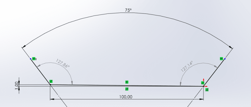
See the image below for a worst case. Here the bent edges are at the 5deg from nominal, but even with the base at its worst allowable perpendicularity, the angle relative to the base is within 0.72deg. Note, the perpendicular tolerance will allow the horizontal line to slide anywhere along the wedge formed by the datum. A profile control in addition to, or in place or, the perpendicular control may be appropriate. Depending on your needs, this could be measured with some accuracy using a digital protractor. This method effectively allows the arms to bend symmetrically but like I said previously, it's may not be appropriate depending on the function. If all you're worried about is where the center of the arcs end up relative to eachother, then this probably isn't the way to go.

Capture6_bggpzp.png


EDIT: A similar effect could be achieved by directly tolerancing one of the angled faces to the horizontal one adding x2 to make the specification symmetrical (eg. 2x 130deg+-2.5deg). Then you could add a note saying the angles must match each other to within 0.5deg, but it's not really a GD&T solution.
 
Ryan said:
I believe defining the angle with an angular tolerance changes the association from theoretically exact to variable in which case your proposed datum feature simulator would work. There are no similar examples provided in the standard for me to verify this. The only example of a wedge is with it being defined by a theoretically exact angle.
If it was an ASME Y14.5 based drawing, I wouldn't recommend defining the angle with a direct tolerance. If the two sides of the wedge are used to establish a common datum, I would suggest making the angle between them basic (theoretically exact), and using a separate datum feature symbol for each side of the wedge, but then referencing the two sides as a "common datum feature" such as A-B to imply a single datum established from both. Of course the mutual orientation nominally defined by the basic angle would also need to be controlled, for which a profile tolerance that applies "2X" to invoke a pattern of the two sides would be used. There are a couple of reasons in this case why I wouldn't recommend a directly toleranced angle per ASME, but the main one is that datum features used to establish any datum reference frame for a geometric control need to have a basic relationship between each other so that the datum simulators can be mutually defined by those basic dimensions. Otherwise, the mutual relationship between the datum simulators is ambiguous.
 
I think the minmax association in ISO handles that ambiguity which you say is present in ASME. The angle between associated planes (datum simulators) would be positioned to achieve the optimal minmax value. What I like about creating the datum directly from the angular feature of size is that the datum plane is defined as the bisector between the associated planes forming the datum allowing perpendicularity to be used, which I'm not sure would be the case under your proposed method.
 
Ryan said:
What I like about creating the datum directly from the angular feature of size is that the datum plane is defined as the bisector, which I'm not sure would be the case under your method.

Under ASME Y14.5, my interpretation would be that datum A-B is a combination of two planes and a line: the two wedge faces would be "contacted" by two theoretical planes at the basic angle between each other, simulated by the inspection equipment, and the intersection line between them would be part of the datum. Then a bisecting plane between the said planes and through the line would be established, to be part of the datum reference frame. A second plane of the datum reference frame would be established through the intersection line and normal to the first plane. If A-B is referenced alone in a feature control frame we wouldn't be concerned where exactly the third plane of the datum reference frame is, but it would be out there, perpendicular to the first two, and anywhere in the "depth" of the part (into or out of the page in the shown view). Finally, these 3 orthogonal planes would define the origin and the axis system used for the geometric controls that reference A-B.
 
SeasonLee,
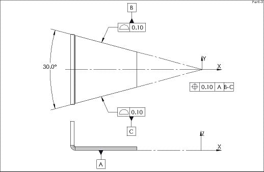
I think in the figure you posted, the two profile feature control frames that control the secondary common datum feature B-C miss a reference to the primary datum feature A.
Also if this drawing was per ASME-Y14.5, I would make the angle basic and then the angular relationship between the two sides of B-C would also be controlled by the two profile FCFs that would reference A (due to a Simultaneous Requirement).
 
Thanks for all of your clarifications, people!

drawoh said:
The symmetry symbol has been removed from the latest version of ASME Y14.5, along with concentricity. I say "good riddance".
Didn't know that... But good to know, thanks!

Ryan said:
If all you're worried about is where the center of the arcs end up relative to eachother, then this probably isn't the way to go.
My main worry is that the profile will be overly asymmetrical (like the red lines as opposed to the black lines) and thus where the center of the arcs end up with respect to the (theoretical) centerline of the part.
Profile_With_Asymmetry_tzhktd_m9qwvt.png


For now I'm guessing this will be my best option:
Ryan said:
A similar effect could be achieved by directly tolerancing one of the angled faces to the horizontal one adding x2 to make the specification symmetrical (eg. 2x 130deg+-2.5deg). Then you could add a note saying the angles must match each other to within 0.5deg, but it's not really a GD&T solution.
Just have to figure out what the easiest way is for operators to measure this.

Other opinions or suggestion still welcome ofcourse!
 
Burunduk,

I've been considering your proposal further and want to explore this more. I think doing the constraint in the manner you have posted - while correct and clear - may restrict tolerance zone more than required. As an example: for the part to function, the tolerance could be +-5deg from the horizontal face to either of the angular faces, but the angles need to match within 0.5deg of each-other (ie. if one is exactly 130deg, the other could be anywhere between 129.5 to 130.5). I think the way I proposed the tolerancing would utilize the full tolerance zone. If constraining the datums to basic profiles it would lose out on a lot of the available tolerance.

EDIT: I was considering this in the context of using the profile with simultaneous requirement to define the faces of datum A & B. If, in SeasonLee's example, the FCF on the face of Datum B was referenced to datum A and had a wider tolerance then I think that would maximize the tolerance zone when referencing A-B. I think relying on simultaneous profile would require a much narrower zone than this approach.
 
Ryan,
That depends on the amount of profile tolerance to be assigned to control the variation of the two angled surfaces. It is possible to specify as much tolerance as required so that the actual angles are free enough to vary. A basic angle would only define the nominal geometry and the datum simulators ("associated planes"?).

Again, it's a sort of constraint when working per ASME that the datum features have to be defined by basic dimensions to each other. But that restriction doesn't cause much trouble. Per ISO the situation seems to be different as you say.
 
Hi, RCor:

How do you define the center line? Is there a feature at middle of the part, like a through hole?

Best regards,

Alex
 
Hi jassco,

No there is no feature, it's just the profile in length with the section as shown in my sketches.
 
Status
Not open for further replies.

Part and Inventory Search

Sponsor