Hi!
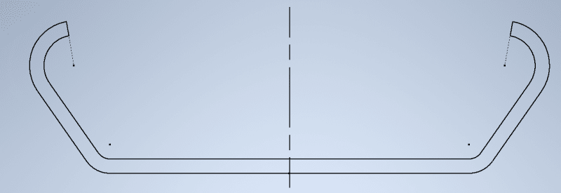
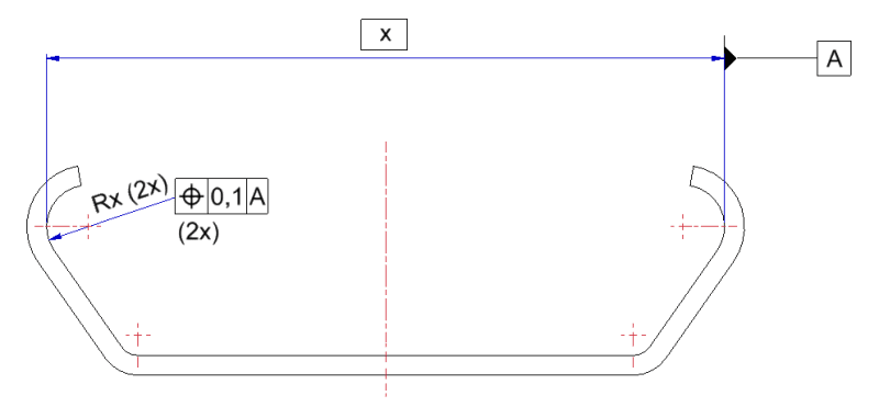
I'm trying to dimension and add GD&T to this cross-section
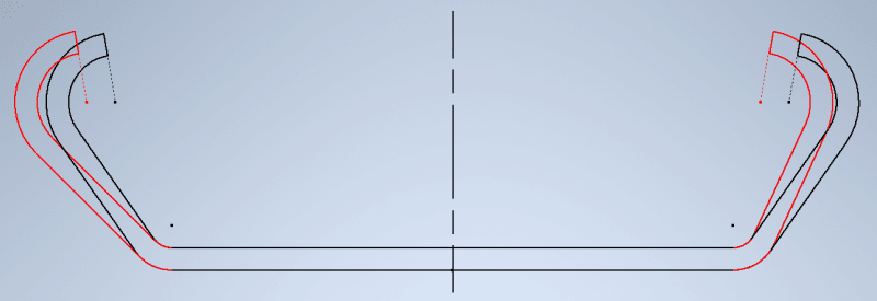
to prevent the left and right from going asymmetrical like this (over-exaggerated)
I've tried several things (see below), but haven't found a good solution that is both correct and measurable by operators (with simple gauge(s) and or caliper).
(Note that I use the upmost dimension as reference since this is the dimension with the smallest tolerance on it)
Option 1 - makes no sense since centerline of referenced dimension moves along with centerline of reference
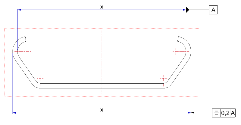
Option 2 - would make more sense, but not sure how this would be measurable
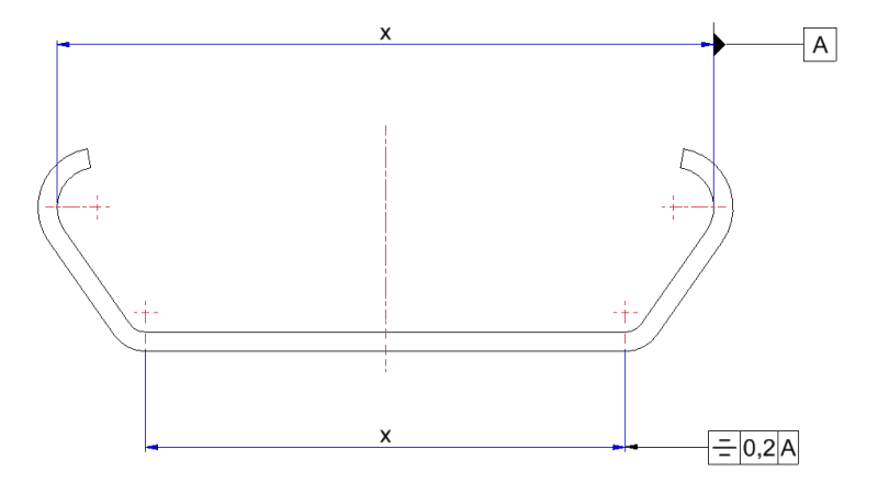
Option 3 - basically like option 1: centerline and position move together
Any tips or advice is very welcome!
Thank you in advance!
I'm trying to dimension and add GD&T to this cross-section

to prevent the left and right from going asymmetrical like this (over-exaggerated)

I've tried several things (see below), but haven't found a good solution that is both correct and measurable by operators (with simple gauge(s) and or caliper).
(Note that I use the upmost dimension as reference since this is the dimension with the smallest tolerance on it)
Option 1 - makes no sense since centerline of referenced dimension moves along with centerline of reference

Option 2 - would make more sense, but not sure how this would be measurable

Option 3 - basically like option 1: centerline and position move together

Any tips or advice is very welcome!
Thank you in advance!
