Eng-Tips is the largest engineering community on the Internet

Intelligent Work Forums for Engineering Professionals

How can I analyse force-displacement data of TPMS lattice structures which vary in cross-section?

Status
Not open for further replies.

AceMae

Student
Feb 8, 2024
3
0
0
AU
Hi,

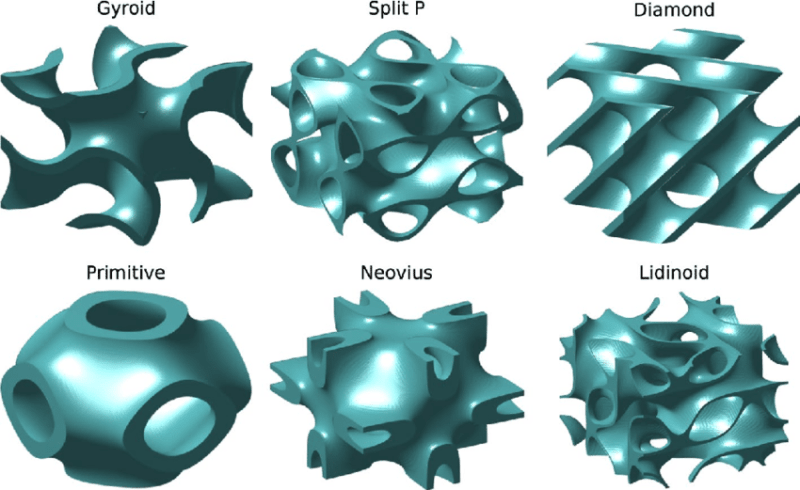
I am trying to figure out how to analyse experimental data collected from compression testing TPMS lattices and account for the specimen's variation in cross-sectional area. When searching online, I mostly find tutorials for FEA analysis or papers that don't really give a comprehensive insight for readers who are not as familiar as the authors.

If someone could please direct me towards resources or roughly how I would go about this I would be really grateful! I am just a bit confused what the process is for structures with such significant cross-sectional area variation as I have not learnt this before? It feels like a gross approximation to use the area calcualted from the minimum diameter measured or even the average diameter of multiple points considering the internal voids.


Replies continue below

Recommended for you

Triply periodic minimal surfaces in the image below.

The-six-triply-periodic-minimal-surface-TPMS-geometries-used-in-this-study-All-at-02_tgfwap.png
 
ok, maybe I'm dumb (let's assume the most basic and go from there) ...

1) what do you mean by "analyze" ? stress ?, frequency ?, fatigue life ??, stiffness ??

2) what experimental data do you have for these (pretty fantastic) shapes ?

"Hoffen wir mal, dass alles gut geht !"
General Paulus, Nov 1942, outside Stalingrad after the launch of Operation Uranus.
 
Nothing dumb about requesting more information, also I am the one asking for help if anything.

Further context:
There are several specimen all with the same bulk geometry dimensions (i.e. a cylinder of the same size) for each of the unit cells. For each specimen of unit cell, there are multiple samples which vary in relative density by latticing the prescibed unit cell at at increased sizes.
For example (not actual dimensions):
@50%RelDen : cell size = 9 x 9 x 9
@40%RelDen : cell size = 7 x 7 x 7

2) Force-displacement data of various relative densities collected from simple uniaxial compression tests by a universal tester. Constant crosshead speed, no ramping. Tensile testing to be completed.

1) Various mechanical properties from processing force-displacement to stress-strain. I have calculated strain, but lets start with stress. Since engineering stress is directly related to the sample's geometry, specifically the cross-sectional area which by convention is idealised as constant along the member, I am unsure what to do when that is not the case throughout the entire sample? Since the unit cells only vary in size to achieve different relative densities, we will assume cell thickness is relatively constant despite potential manufacuting discrepencies. If we consider the cross sectional area at several differential amounts along the z-direction of the cylinder, they would all be different as the structures vary periodically in all three axes (a defining characteristic of TPMS). Wouldn't using the nominal diameter to calculate the cross-sectional area and find stress as a bulk material produce inaccurate values for stress and subsequently anything which depends on it or area? As a general, I am not sure what should be done when calculating stress using experimental data for a member that constantly varies in crossectional area or even in lattice structures.
 
If the cross section needs to have a relatively large number of unit cells, then you can just use the (artificial) total area to get an “averaged” stress.
If only a small number of unit cells, then you have a difficult problem.
What are you planning to do with the calculated “stressl?
 
Status
Not open for further replies.
Back
Top