Continue to Site

Eng-Tips is the largest engineering community on the Internet

Intelligent Work Forums for Engineering Professionals

  • Congratulations pierreick on being selected by the Eng-Tips community for having the most helpful posts in the forums last week. Way to Go!

How Can You Generate This Waveform?

Status
Not open for further replies.

tetwin11

Mechanical
Jan 9, 2012
51
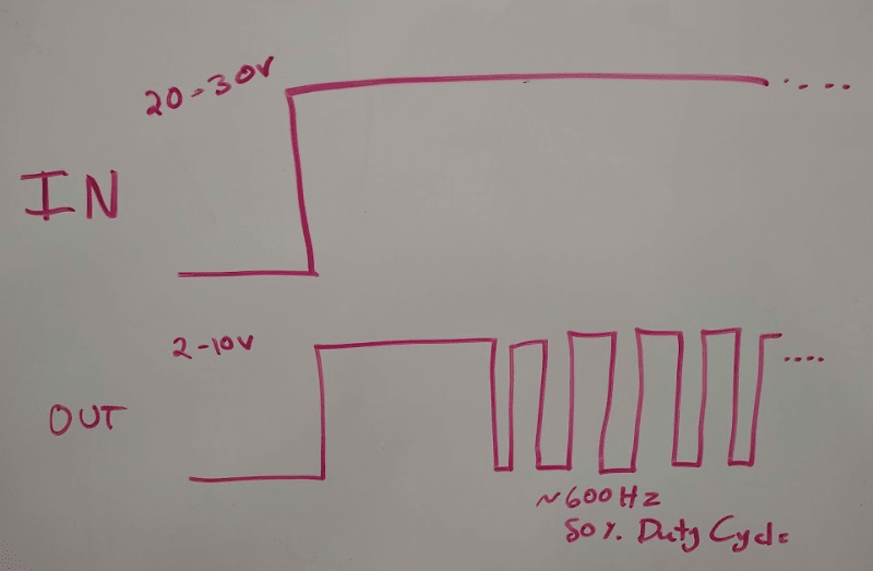
I'm looking to make a circuit that takes a 20-30VDC input and, when that goes high, generates a signal that also goes high, but to a different voltage (2-10VDC). Then after some time of being high, I want it to transition to a 600Hz, 50% duty cycle PWM.

I'm thinking of a monostable 555 and an astable 555 with the outputs diode or'd together. Powered off a linear regulator to drop down the input voltage. This seems a bit inelegant. Any other concepts of how this might get accomplished?

Thanks!

Untitled_g9sevh.png
 
Replies continue below

Recommended for you

You have 3 degrees of freedom in that waveform, but I would use a real OR gate rather that diodes. Alternately, as suggested in answers to a similar question somewhere on this site, is to use a microcontroller, which would get rid of the passive components, although the overall complexity obviously grew an order of magnitude. Nevertheless, a microcontroller would allow programming of the degrees of freedom in real time.

TTFN (ta ta for now)
I can do absolutely anything. I'm an expert! faq731-376 forum1529 Entire Forum list
 
Thanks for the note. I did consider going the microprocessor route, but I feel like that puts this project a good bit out of my comfort range.
Thanks for suggesting the OR gate rather than diodes. I've never used a gate before. Shows how green I am in this realm.
 
An Arduino-based solution isn't THAT complicated, and there are lots of programming examples on the web. Nevertheless, a dual 555 solution is the easiest, but you'll probably be hunting and pecking on resistor/capacitor values for a bit.

TTFN (ta ta for now)
I can do absolutely anything. I'm an expert! faq731-376 forum1529 Entire Forum list
 
Does the range of input voltage matter?
You've specified 20-30V to turn on, but does that mean that 18V does not turn it on, or the other device generating the input signal "can't" produce anything less than 20V? The difference would lead to different setup of the input. Inputs to electronic circuits are often "filtered" in some way, but by that I don't mean just against noise, I mean that it may exclude input ranges that aren't suitable. A resistor followed by a 20V zener to ground would prevent 18V from turning on your circuit. It might be important to have that, or it might be irrelevant (eg. input source comes from a 24V battery).

Afterthougth:
Similar logic applies to the maximum of the range, which you give as 30V. Do you mean the input can't go above that, or that you wouldn't want your device to respond to 32V when it does happen?

 
IRstuff, point taken about the Arduino solution. It wouldn't be that bad.

SparWeb, thanks for the questions and comments. The input is from a 24VDC nominal battery, which might range between 20 and 30V. So the circuit must respond to anything in that range. It's okay if it also responds to something outside of that range.
 
Trinket is about the size of your thumb. Several analog inputs and digital I/O. The digital I/O will output your square waveform. There may actually be a "PWM" output capability ready for you in the programmer. You'd have to check the details though. Write programs in a language similar to C.
For extreme simplification, I'm certain you can use an 8-pin PIC microcontroller to do this. PICAXE is a hobbyist-oriented kit, programmable in BASIC.

 
Status
Not open for further replies.

Part and Inventory Search

Sponsor