Navigation
Install the app
How to install the app on iOS
Follow along with the video below to see how to install our site as a web app on your home screen.
Note: This feature may not be available in some browsers.
More options
-
Congratulations waross on being selected by the Tek-Tips community for having the most helpful posts in the forums last week. Way to Go!
You are using an out of date browser. It may not display this or other websites correctly.
You should upgrade or use an alternative browser.
You should upgrade or use an alternative browser.
How do I create a surface out of this geometry?
- Thread starter Kimpan
- Start date
- Status
- Not open for further replies.
- Thread starter
- #3
I have an academic version of SE so you might not be able to open it. Should I upload the iges?
beachcomber
Mechanical
Yes upload the iges
bc.
2.4GHz Core2 Quad, 4GB RAM,
Quadro FX4600.
Where would we be without sat-nav?
bc.
2.4GHz Core2 Quad, 4GB RAM,
Quadro FX4600.
Where would we be without sat-nav?
- Thread starter
- #5
Have you done the built in tutorial?
It's pretty limited but got me started.
It's pretty limited but got me started.
Posting guidelines faq731-376 (probably not aimed specifically at you)
What is Engineering anyway: faq1088-1484
What is Engineering anyway: faq1088-1484
Kimpan,
Check out this site
There are a number of surfacing tutorials including the use of guide curves. Helped me a lot when I first started using SE.
Jason
Check out this site
There are a number of surfacing tutorials including the use of guide curves. Helped me a lot when I first started using SE.
Jason
beachcomber
Mechanical
Try the Options button on the Save As dialog - there may be settings that are not set to output wire-frame geometry.
bc.
2.4GHz Core2 Quad, 4GB RAM,
Quadro FX4600.
Where would we be without sat-nav?
bc.
2.4GHz Core2 Quad, 4GB RAM,
Quadro FX4600.
Where would we be without sat-nav?
beachcomber
Mechanical
You are going to struggle to get a really smooth surface but there are a couple of ways.
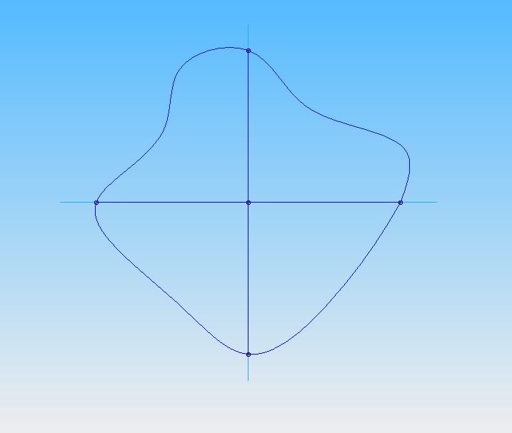
First way would be to split the base priile at each of the 4 points you have shown.
Then split the 2 other curves where they intersect at the top.
You can then create surface using the 'Surface by Boudary' command.
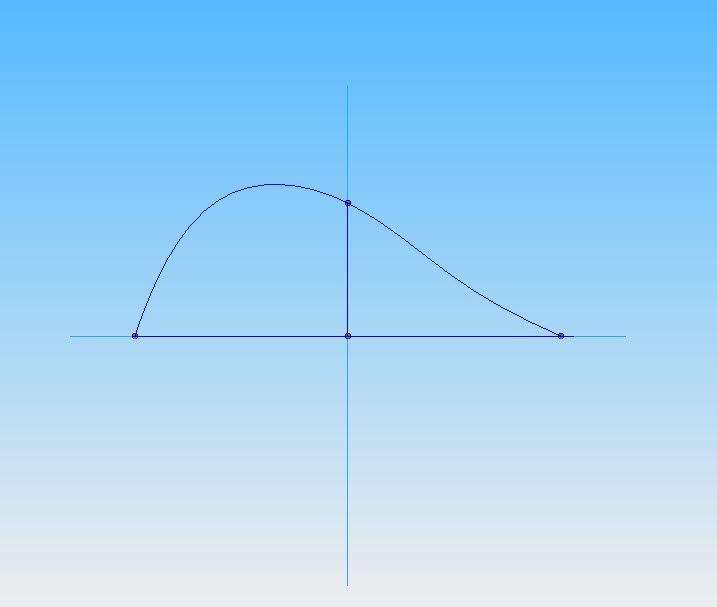
Another way would be to split the base curve at 2 points - ie. at each end of the curve that you haven't shown a true view on. The one you have shown as a true view will be the path curve.
Then use the Blue Surf command using 3 cross-sections and one path curve.
You would define the cross sections in the order first base curve, cross curve, other base curve.
I will try and post an example tomorrow.
bc.
2.4GHz Core2 Quad, 4GB RAM,
Quadro FX4600.
Where would we be without sat-nav?
First way would be to split the base priile at each of the 4 points you have shown.
Then split the 2 other curves where they intersect at the top.
You can then create surface using the 'Surface by Boudary' command.
Another way would be to split the base curve at 2 points - ie. at each end of the curve that you haven't shown a true view on. The one you have shown as a true view will be the path curve.
Then use the Blue Surf command using 3 cross-sections and one path curve.
You would define the cross sections in the order first base curve, cross curve, other base curve.
I will try and post an example tomorrow.
bc.
2.4GHz Core2 Quad, 4GB RAM,
Quadro FX4600.
Where would we be without sat-nav?
- Thread starter
- #10
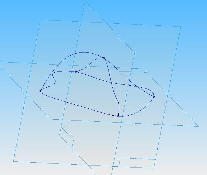
Since I couldn't export wireframes in the IGES format I just made a protrusion out of each sketch. Beachcomber, thanks for your efforts! If you want, could you take a look at the iges file I attach here and see if it is possible to make a surface out of that kind of geometry? An enclosed base with multiple crossing guidelines (3 in this case).
- Thread starter
- #11
Good morning everyone.
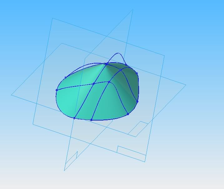
Kind of a slow morning so I had some time to play around with this. Attached is the surface I managed to come up with (in .igs and .par). I used the derived curve command to place the curves and then created three blue surfs which used the appropriate transverse curve as a guide. Then stitched the whole thing together.
There are options in the blue surf command to control the beginning and end of the surfaces (normal to or parallel to) so with a little effort you may be able to tweak the appearance.
Does this help?
Jason
Okay, only one file at a time...
Here's the .igs
Here's the .igs
- Thread starter
- #14
Thanks for that jjengel.
I thought there would be a simple way to create surfaces like this but I guess you have to devide the whole thing into separate surfaces. This should be quite cumbersome when dealing with many guidelines.
I am looking to model the inside surface (in contact with the head) of a bicycle helmet where I start with the iges file of a helmet. I think it will be quite time consuming if I have a lot of guidelines.
Do you guys have any recommendations for how I could do this in a simpler way maybe?
Maybe I'm missing something, but given the geometry you're starting with I don't see any easier way to accomplish this task. But my SE surfacing skills haven't gotten a lot of use (ever).
You could always pattern a curve along another curve and then just create a blue surf using each occurance. It would be quicker, but I don't see a good way of doing it given the current curve set. Seems like it would better suited to a symmetric part.
You could always pattern a curve along another curve and then just create a blue surf using each occurance. It would be quicker, but I don't see a good way of doing it given the current curve set. Seems like it would better suited to a symmetric part.
beachcomber
Mechanical
Attached part file containing BlueSurf.
I have used simple curves here.
The Cross-section curves are the base profile and a Point at the top intersection.
The path curves are the 4 curves joining the base to the top point.
Hope this helps.
bc.
2.4GHz Core2 Quad, 4GB RAM,
Quadro FX4600.
Where would we be without sat-nav?
I have used simple curves here.
The Cross-section curves are the base profile and a Point at the top intersection.
The path curves are the 4 curves joining the base to the top point.
Hope this helps.
bc.
2.4GHz Core2 Quad, 4GB RAM,
Quadro FX4600.
Where would we be without sat-nav?
- Thread starter
- #17
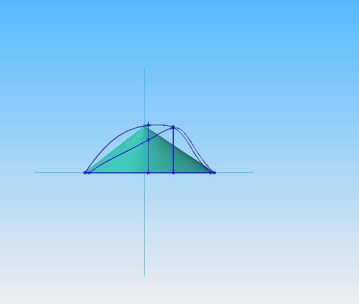
Thx beachcomber, that works great when having 2 intersecting curves. Do you know if it's possible to add more intersecting curves to be able to define the shape of the surface more?
I tried your method out but as soon as I try to apply more than those two guide curves I get an error like:
"The selected geometry does not touch all the cross sections and therefore is not valid. Each guide curve must touch all of the selected guide curves."
I tried your method out but as soon as I try to apply more than those two guide curves I get an error like:
"The selected geometry does not touch all the cross sections and therefore is not valid. Each guide curve must touch all of the selected guide curves."
beachcomber
Mechanical
In my example you would create additional cross-sections that are on a parallel plane to the base profile.
The guide curves would then also have to intersect with this cross-section.
Additional guide curves can be created but again they must intersect the cross curves.
I suppose any path curve lying on an angled plane or even not planar would be OK.
What you are trying to achieve is a set of 'slices' for the cross-sections and they don't really have to be exactly parallel slices.
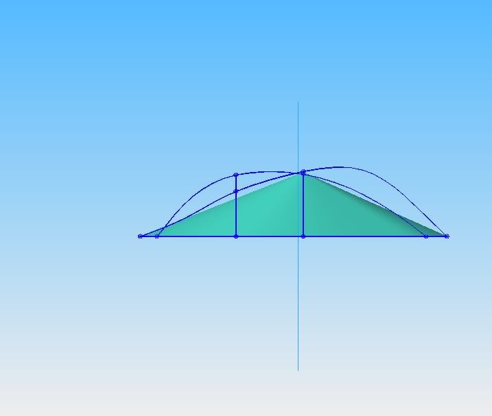
What you have shown is not acceptable because your 2 additional curves do not intersect the top point.
If you have a set of curves forming a mesh (similar to what your 2 additional curves are doing) you could always create more cross-sections by joining the mesh intesection points.
I'll try and add some into the example.
bc.
2.4GHz Core2 Quad, 4GB RAM,
Quadro FX4600.
Where would we be without sat-nav?
The guide curves would then also have to intersect with this cross-section.
Additional guide curves can be created but again they must intersect the cross curves.
I suppose any path curve lying on an angled plane or even not planar would be OK.
What you are trying to achieve is a set of 'slices' for the cross-sections and they don't really have to be exactly parallel slices.
What you have shown is not acceptable because your 2 additional curves do not intersect the top point.
If you have a set of curves forming a mesh (similar to what your 2 additional curves are doing) you could always create more cross-sections by joining the mesh intesection points.
I'll try and add some into the example.
bc.
2.4GHz Core2 Quad, 4GB RAM,
Quadro FX4600.
Where would we be without sat-nav?
- Status
- Not open for further replies.
Similar threads
- Replies
- 0
- Views
- 31
- Locked
- Question
- Replies
- 0
- Views
- 26
- Replies
- 0
- Views
- 18
- Replies
- 0
- Views
- 23