Eng-Tips is the largest engineering community on the Internet

Intelligent Work Forums for Engineering Professionals

How do I move this 1000lb gantry along the rails without jamming? 1

Status
Not open for further replies.

Imposter666

Mechanical
Jan 15, 2021
36
0
0
CA
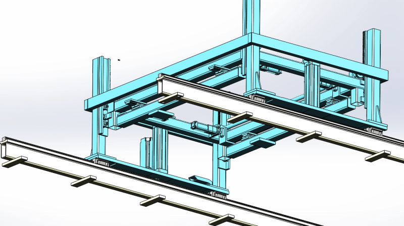
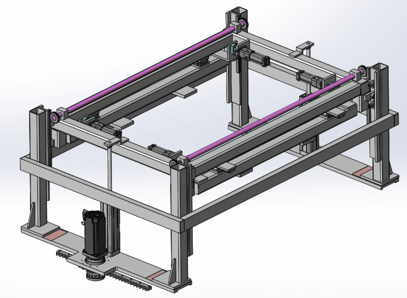
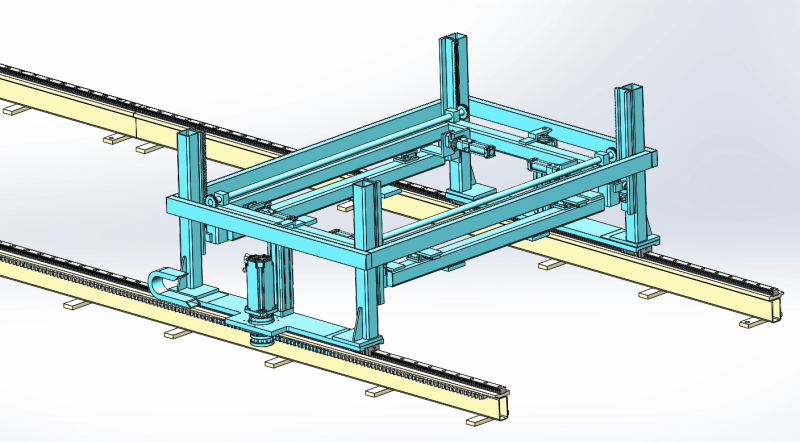
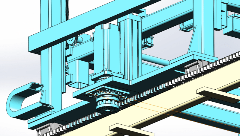
In the previous post, I had asked how to design the lift mechanism of this gantry []. Now I need your input how to move this mechanism 8 meters along the rails. For now, I have both sides resting on LM guides driven by a single motor on one side. There are objects between the LM guides so I can't connect the leg structures. In practice, it is extremely difficult to align the seats for the LM guides once installed on the ground. So I need to come up with a mechanism with more 'give'. I am thinking to switch to some kind of mechanism with rollers. What do you think of this idea? Do you have any suggestions?
Some input:
Rails are 2.5m apart.
Distance is 8m long.
This needs to be very sturdy mechanism with high cycle count.
Blue section is going to be close to 1000lb with the load it will carry.

7_i7sodo.png
4_d96rme.png
6_ifhlqp.png
8_zixcwv.png
 
Replies continue below

Recommended for you

Let's say I manage to fit in another servo motor and gearbox on the other side. This will synchornize the drive. But what can I replace the LM guides with? Something that gives medium accuracy and easier to align that LM guides.
 
I second the motion to have a single LM guide with opposite side running on a plain roller (cam follower, yoke roller, caster, etc., if necessary, a secondary roller arrangement could be added to counter any uplift forces.) Let the LM guide do all of the alignment. Check that moment capacity of the LM guide(s) exceeds the frictional moment created by the rolling resistance of the plain wheel on track times the moment arm. The roller pinion shown seems like a nice system, where there is just one drive on the LM guide side.
 
How fast doe it need to move? How dirty is the environment? Is the location easy to get to for maintenance? Ball screws and ball screw followers are common.
 
one drive gear is one solution.

Is it really That hard to have two independent drives. The teeth on the two tracks don't need to be aligned (since the two drive heads aren't). Ok, the trick might be in synchronizing the two drives, but one on switch and equal lengths of cabling, no?

But I would add a 3rd smooth idler wheel (on the inside of either (both?) tracks).

"Hoffen wir mal, dass alles gut geht !"
General Paulus, Nov 1942, outside Stalingrad after the launch of Operation Uranus.
 
Obviously you're on the mechanical side of the design but you really should try to coordinate with the electrical side. You can use VFD's with shaft encoders to provide synchronized movement between two motors without expensive mechanical interconnections.
 
Hi imposter666

Like others have said a single shaft connected to both sides with a rack and pinion and two gears

“Do not worry about your problems with mathematics, I assure you mine are far greater.” Albert Einstein
 
I am still figuring out how the reply system works on this website. Seems like I am not able to reply to individual messages. Let me know if I am missing something.
To answer the questions directed at me:
1. The other side without servo drive needs to be as narrow as possible as it will pass through tight spaces
2. The middle of the rails have objects along the rails, so I can't physically connect the rails. The rails needs to be individually installed on the ground and gantry sits on them. That's why I think aligning the rails will be a big problem. I have designed such 2 rail systems for robot transfers and use LM guides on both sides. But their structures have always been weld connected and machined together for alignment
3. For LM guides on one side and Rollers on the narrow side: I was looking at the rollers yesterday. That's what I am leaning for at the moment.
 
This forum is a single thread per topic; no individual replies. You can quote (little guy with a talk balloon icon) and then copy/paste what you want.

 
I think you're getting wrapped around the axle on a non-issue..

alignment of linear guides is an age-old problem. Every vendor has design practices in their design manuals which make installation easier. Follow them, and the alignment problem goes away.

With well-aligned ball bearing guides I would not expect to need a drive on both sides.
 
If the horizontal motion is being driven by two servomotors, they can be tied together electronically (one master, one slave) effectively creating an electronic "connecting shaft" between the two.
 
Unless acceleration plays a huge role in the forces generated, a 1000 lb load will have minimal frictional resistance - even an unrealistically high 10% would only be 100 lb. Surely the frame can be made stiff enough to withstand a 50 lb force, which is half of the total frictional load applied to the non-drive side, with minimal deflection. Still not convinced of the need for two drives.
 
Status
Not open for further replies.
Back
Top